
How to Build an Inverter Circuit with an 7404 Chip
In this project, we will show how to build a inverter circuit using a 7404 hex inverter chip.
An inverter circuit is a circuit that changes the logic state of an input to the opposite state.
So, for example, if you feed a LOW logic state signal into the inverter, it will output a HIGH logic signal. If you feed a HIGH logic signal into the inverter, it will output a LOW logic signal.
This may be necessary for several different reasons, but in the final reasoning of things, it's because you want the opposite logic state that the device offers.
For example, a device outputs a LOW logic state voltage when triggered. And the device that reads the voltage is active HIGH device. Therefore, you need the opposite logic state of the LOW signal to trigger the device that reads the voltage. Therefore, you pass the LOW logic state signal through an inverter, which inverts it into a HIGH logic state signal. The device that's now active HIGH can be triggered on.
So, the basic rule is, any time you need the opposite logic state signal in order for a circuit to work, you can use an inverter to flip the logic state signal to the opposite state.
You'll see if you build a lot of circuits that this definitely will be necessary.
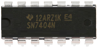
The inverter chip we will use is an 7404 inverter. We describe this in detail below.
Components
- 7404 Hex Inverter Chip
- NPN Inductive Proximity Sensor
- 2N3904 NPN Transistor
- 6V Buzzer
The 7404 is a hex inverter chip, which means it's composed of 6 independent inverter gates.
Each gate is composed 1 input and 1 output.
The 7404 should be fed a minimum voltage of 4.5V and a maximum voltage of 5.5V.
The pinout of the 7404 is shown below.
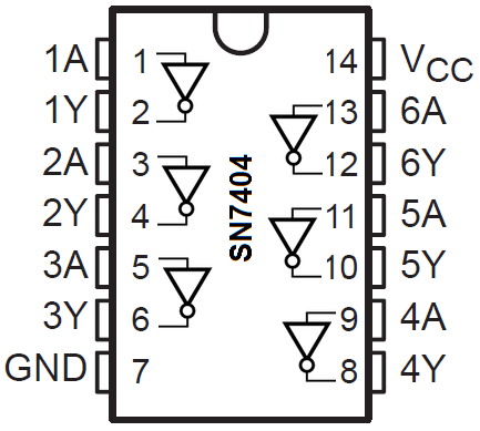
You can see based on the pinout that there are 6 inverter gates. Each one has 1 input and 1 output.
The output from the gate will be the opposite logic signal from the logic signal received at the input of the gate. So if a logic LOW is fed into the gate, a logic HIGH will be output. If a logic HIGH is fed into the gate, a logic LOw will be output.
This summarized in the table below.
| Inverter Truth Table | |
| Input | Output |
| L | H |
| H | L |
So you can see that the logic signal output by an inverter gate is the opposite of the logic signal fed into the gate.
The A's of each gate are the input and the Y's of each gate are the outputs. Y=
For an input into the inverter gate of the 7404 chip, the maximum voltage in order for it to be read as an LOW logic state is 0.8V. So this is the maximum voltage in order for it to read it as a Low logic state. For a HIGH logic state, the minimum voltage fed into an input is 2V. So 2V is the minimum voltage necessary for the 7404 chip to read it as a HIGH logic state. So that's mean between 0.8 and 2V is a gray area that should be avoided. We want 0.8V or less for a LOW logic signal and 2V or more for a HIGH logic signal.
So now that we know all of this, let's assemble an actual circuit.
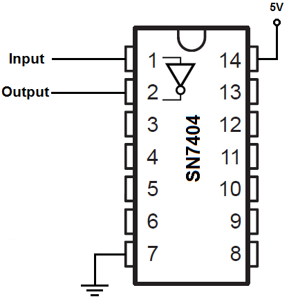
7404 Inverter Circuit
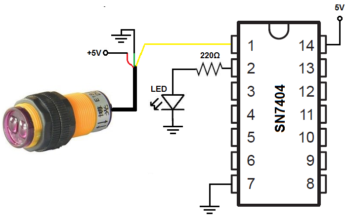
The inverter circuit we will build with an 7404 is shown below.
The breadboard circuit of the circuit shown above is shown below.
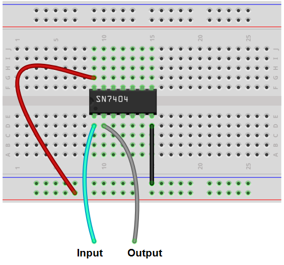
So again, this just shows to demonstrate the connections for a 7404 inverter chip.
An actual and great example of when you would need a inverter is when using an infrared proximity sensor switch.
An infrared proximity sensor switch is a switch that detects objects in front of it.
The infrared proximity sensor switch has 3 pins, 2 for power and 1 for a signal line.
When no object is in front of the proximity sensor, it outputs about 3.5V on the signal line.
When it detects an object in front of it, it outputs about 0.07V, which is nearly 0V.
So it outputs a HIGH signal when there is no object and outputs a LOW signal when it detects an object.
This is normally a problem with devices that are active LOW. Since most devices are active HIGH, meaning they are triggered by a HIGH voltage, having a device that outputs a LOW voltage when triggered off is problematic. The solution is to use an inverter to switch the logic states of the active LOW device. So in the case of an infrared proximity switch, which is active LOW (it outputs a LOW voltage in response to detecting an object), we can switch the output logic state to HIGH with an inverter. So we use an inverter and with an inverter, it now functions as an active HIGH device.
This is why inverters are so necessary.
To see the inverter circuit with the infrared proximity switch, see the following circuit: 7404 Inverter Circuit with an Infrared Proximity Switch Sensor.
And this is why inverters such as the 7404 is so important in circuits.
Related Resources
How to Build a PNP Inductive Proximity Sensor Circuit