
How to Build a 74HC238 3-to-8 Decoder Circuit
In this project, we will show how to connect an 74HC238 3-to-8 decoder/demultiplexer to a circuit.
Using this decoder/demultiplexer, we can control 8 outputs with just 3 pins.
This is also the reason why decoder/demultiplexer chips are great additions to microcontrollers. With just 3 pins on the microcontroller being used, it adds 8 outputs. So it's a gain of +5 pins. So it functions as a output port expander.
In this circuit, though, we will not be incorporating it into a microcontroller but instead just show how control with the 74HC238 can be done manually with pushbuttons.
In this project, we will show how a 74HC238 decoder works and how we can manually control it with 3 pushbuttons.
Using 3 pins, called the address pins, we can create a total of 8 different outputs. This is because 23= 8.
Our output devices will be LEDs. Since there are 8 outputs on the 74HC238 chip, we will attach 8 LEDs to the chip. One output will have an LED along with a series-limiting resistor to limit excess current to the LED>
How the circuit works, in a nutshell, is there are 3 address pins, pins A0, A1, and A2. These address pins control which output pins turn on. So, again, with 3 pins, we can control 8 outputs.
The 3 pins can be in either 1 of 2 states. They can either be LOW (tied to GND) or HIGH (tied to VCC).
So if we have an address pin connected to ground, it has a value of 0. If an address pin is connected to +5V, it has a value of 1.
So if all address pins are connected to ground, this gives a value of 000. This equates to all the outputs (LEDs) being off.
If the address pins have a value of 001, this equates to the first LED being on.
If the address pins have a value of 010, this equates to the first 2 LEDs being on.
If the address pins have a value of 011, this equates to the first 3 LEDS being on.
If the address pins have a value of 100, this equates to the first 4 LEDs being on.
If the address pins have a value of 101, this equates to the first 5 LEDs being on.
If the address pins have a value of 110, this equates to the first 6 LEDs being on.
If the address pins have a value of 111, this equates to all 7 LEDs being being on.
And this how the address pins can affect all 8 outputs.
We will go into all the more details below.
But a 74HC238 is a very useful chip that has a lot of capabilities.
Components
- 74HC238 3-to-8 Decoder Chip
- 3 Pushbuttons
- 3 1KΩ resistors
- 8 220Ω resistors
- 8 LEDs
The 74HC238 3-to-8 decoder chip can be obtained for under $1 on ebay.
It is a 8-pin chip.
The datasheet for this chip can be found at the following link: 74HC238 Datasheet.
The pinout of the 74HC238 is shown below.
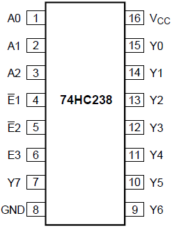
The 74HC238 can be powered with +5V. Therefore, we can connect VCC to We connect VSS to ground. This completes the powering that's necessary for the 74HC238.
The A0, A1, and A2 pins are the address pins. These are the pins which are used to control the outputs of the chip. It follows a binary-to-decimal code.
So if all address pins are HIGH, this equates to a value of 111, which in decimal is 7. So when all address pins are HIGH, all 7 LEDs will be on.
If the A0 is HIGH, A1 is LOW, and A2 is HIGH, this equates to a value of 101, which in decimal is 5. So when the address pins are 101, 5 LEDs will be on.
The address pins are kind of the center of control.
The enable pins are the pins that allow for outputs to be able to turn on when
The rest of the pins, Y0 to Y7, are the output pins. To these pins, we connect an LED along with a series-limiting
resistor to limit excess current to the LEDs, so they don't get blown out.
74HC238 3-to-8 Decoder/Demultiplexer Circuit with Manual Pushbutton Control
The 74HC238 3-to-8 decoder/demultiplexer circuit we will build with
manual pushbutton control is shown below.
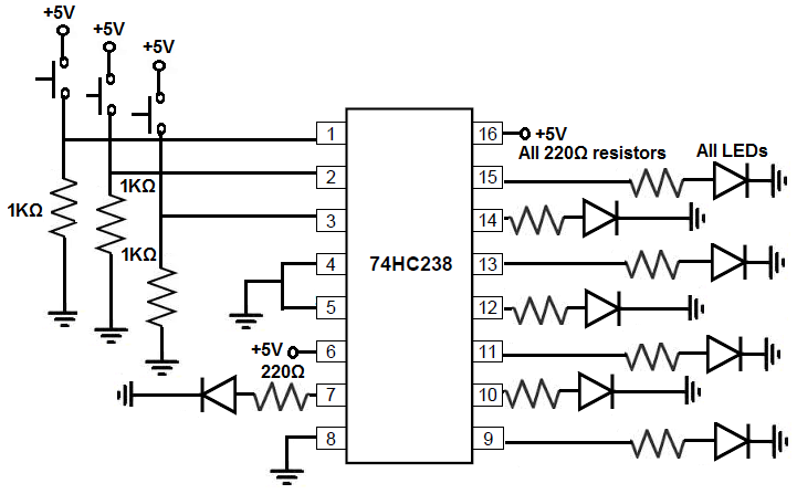
We will now explain the hardware connections.
First to connect power, we connect VCC to +5V and GND to ground.
The first 3 pins of the microcontroller are A0, A1, and A2. To each of these pins, we connect a pull-down resistor. A pull-down resistor is a resistor that is normally LOW but when a pushbutton connected to it is pressed becomes HIGH. So without us pressing down on the pushbutton attached to the pull-down resistor, it will be in a LOW state (connected to GND). With the pushbutton being pressed down, it gets pulled to a HIGH state (connected to +5V).
The next 3 pins are the enable pins,
The rest of the pins, Y0 to Y7, are outputs. To each of these we connect an LED and a series-limiting resistor.
How the circuit works is the pushbuttons control the outputs. Without any pushbutton being pressed, all the LEDs are off. If we press down on the pushbuttons, the corresponding LEDs will turn on in a binary-to-decimal format.
If we push down on the first 2 pushbuttons attached to A0 and A1, this gives a value of 011 to the address registers. This is the equivalent in decimal of 3, so the first 3 LEDs turn on.
You have to know binary and decimal equivalents to really work with this well. But once you do, it's very simple
and straightforward to work.
Related Resources
How to Connect a 74HC238 3-to-8 Decoder to an Arduino Microcontroller