
What are ADC Regular Sequence Registers?

In this article, we explain what ADC regular sequence registers are and how they are used for analog-to-digital (ADC) conversion.
ADC regular sequence registers decide the sequence of sampling from ADC components connected to a microcontroller.
Say, for example, you have multiple analog devices connected to a microcontroller such as STM32 discovery board. You then can sample the analog values from these analog devices in a particular sequence. This is where the ADC regular sequence registers comes in.
If we have a temperature sensor, a humidity sensor, and a moisture sensor, we can set up a sequence that the temperature sensor be sampled first, then the humidity sensor, and then the moisture sensor.
Even if there is only a single analog device connected to a microcontroller board, then you still use the ADC regular sequence register, specificying a single device to be sequenced.
Below are the ADC regular sequence registers for the STM32F407G discovery board.
The STM324xx discovery boards have 3 ADC regular sequence registers.
These registers are ADC regular sequence register 1, ADC regular sequence register 2, and ADC regular sequence register 3.
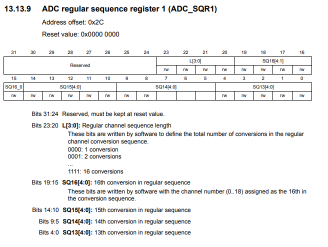
Below is the ADC regular sequence register 1.
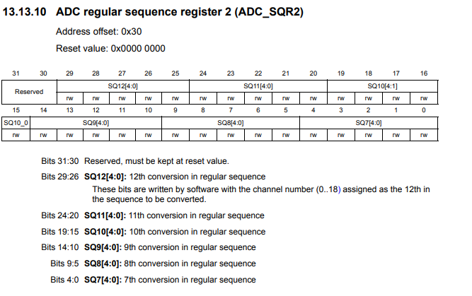
Below is the ADC regular sequence register 2.
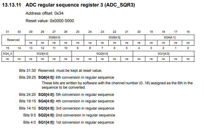
Below is the ADC regular sequence register 3.
SQ1, the first 4 bits of the register, is the first sequence of the ADC sampling. SQ2 would be if you have another ADC component. SQ3 would be if you have a third ADC component, and so on.
Within the regular sequence registers, you specify the ADC channels you are using.
There are 16 possible ADC channels which can be selected.
As an example, let's say that we want to sample from the analog device connected to channel 8, then sample from the analog device connected to channel 12, and then sample from the analog device connected to channel 9.
In this case, you want the first ADC sampling to come from channel 8; thus, for SQ1, we specify 1000, which is the binary for 8.
Next, we want to sample from channel 12; thus, for SQ2, we specify 1100, which is the binary for 12.
Next, we want to sample from channel 9; thus, for SQ3, we specify 1001, which is the binary for 9.
And this can be continued for up to 16 conversions or sequences.
You can see this in the 3 registers as the sequences go from SQ1 to SQ16.
If you are working with a single ADC component connected to a single channel, then you would just specify the ADC channel used in SQ1 and not have any values for any other registers.
So if you are using ADC1 as the first (the only) sequence, we set bit 0 to 1.
The next thing we need to do is specify the sequence length (how many elements we are doing ADC sampling from).
This is done through the ADC regular sequence register 1.
Bits 20 to 23 control the regular channel sequence length. This determines the total
number of conversions in the regular channel conversion sequence. So if you are sampling from 3 devices, the regular
channel sequence length would be 3. Therefore,
we set bits 20 to 23 to 0011. If you are sampling only from a single device, then the regular channel sequence length
would be 1.
And this is what ADC regular sequence registers are, what they do, and how they are used for
microcontrollers boards such as the STM32 discovery boards.
Related Resources
How to Set Bits of a Number in C
How to Clear Bits of a Number in C