
How to Build an ADXL345 Accelerometer Circuit using the SPI Protocol with an STM32F446 Microcontroller Board in C
In this article, we explain how to build an ADXL345 accelerometer circuit using the SPI protocol with an STM32F446 microcontroller board in C.
A SPI driver allows us to communicate with a device that uses the SPI communication protocol.
In our example, we will use our STM32 board as the master device and communicate with a slave device, an ADXL345 accelerometer. We will get information from this slave device to know its position.
The SPI, which stands for Serial Peripheral Interface, communication protocol is a four-wire interface protocol that has 4 lines of transmission, CLK, SS, MOSI, and MISO.
CLK is the serial clock line, which is used for synchronizing data transfer between the master and slave.
SS is the slave select, which is used to select the slave device. Because we are only working with one device in this circuit, then SS is not of much importance.
MOSI, which stands for Master Out Slave In, is the line in which the master device (STM32 board, in this case) sends data to the slave device.
MISO, which stands for Master In Slave Out, is the line in which the slave device (STM32 board, in this case) sends data to the master device (or how the master device receives data from the slave device).
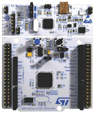
In our sample program, we will use an STM32 board with an ADXL345 accelerometer.
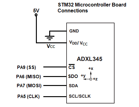
Because the ADXL345 accelerometer, as pretty much all components need, require power, we need to connect the component to +5V and GND, in order to power it.
Because we are using the SPI communication protocol, which is a four-wire protocol, we need to make 4 connections, CLK, SS, MOSI, and MISO, to establish SPI communication between the STM32 board and the ADXL345 accelerometer.
The diagram below was taken from the datasheet for the ADXL345 accelerometer and it shows the connections needed
for SPI communication.
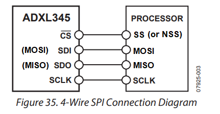
So, in total, 4 wire connections are needed between the STM32 board and the acceleromter, plus the connections for power.
The circuit schematic for the circuit we will build is shown below.
So, after this hardware connection is made, the only thing we need now is the software to execute on the board.
We should then be able to read the positional data that the accelerometer gives us. The ADXL345 is a 3-axis accelerometer. So we get back x data, y data, and z data, which gives us the 3-dimensional data of the tilt or position of the accelerometer at any given time.
So below is the code needed in order to run this accelerometer circuit.
Before we go directly into our main C code, there are some supporting files we need, including register maps and macros needed.
Below we have the stm32f446.h file, which contains many register maps (including for the
SPI register) and macros needed for the software program.
In the next file, adxl345.h, we have macros that are completely specific to the ADXL345 accelerometer.
This is shown below.
So we now have all the supporting files.
So we can now go to our main.c file.
So we now go through the code.
So we first include the header files we need.
We then have a list of the function prototypes, so that the compiler knows about them, as in what they return and what parameters they take in, as well as the parameter types.
We then define a number of variables, which we use in our program. We will get back to these, as well as the main() function.
Instead now we skip ahead to the spi_gpio_init() function, which initializes the SPI communication protocol so that we can use it to communicate with the ADXL345 accelerometer device.
We first enable clock access to GPIOA, because we use these pins in alternate function mode to represent the various SPI pins needed for SPI communication.
We then set pins PA5, PA6, and PA7 in alternate function mode using the MODER register.
We then set these pins to AF5 in order to get the SPI pins that we need. PA5 will represent the SPI clock. PA6 represents MISO. PA7 represents MOSI.
We then go to our next function, spi1_config()
We enable the clock for SPI1.
Next, we work extensively with the SPI control register 1, so we show this now below.

So the next thing we do is we set the clock rate to 4MHz rate.
We can set this to any rate we want the SPI communication to run at; in this case, we simply set it to 4MHz. Remember that PCLK is 16MHz by default. We divide this by 4 to get a frequency of 4MHz.
We set the CPHA bit to 1 and the CPOL bit to 1.
Since we want communication to be bidirectional, we enable full duplex mode. This allows the master to both send and receive data.
We decide to transmit the most significant bit (MSB) first, so we set bit 7, the LSBFIRST, to 0.
We set SPI to master configuration, so that everything is done from the perspective of the master.
We then set the data frame to 8-bit data frame format (instead of 16 bits).
We then enable software management of the SS (Slave Select) pin, so that we can select its value through software and not through hardware. This makes the hardware a little simpler. Setting the SSM bit, bit 9, to 1 enables software slave management. The value that the SS pin will have is equal to the value fed into the SSI bit, bit 8.
We then enable SPI communication.
We then go to the spi1_transmit() function, which allows us to transmit data.
This function takes in 2 parameters, data, which represents the actual data, and the size, which represents how many bytes, or pieces of data, there are.
This data is written to the data register (DR).
Our next function is the spi1_receive() function which takes in the same parameters as the transmit function, data and size.
We read in the data from the data register (DR).
We then have our cs_enable() function, which selects our slave device, so that it can transmit or receive data.
We then have our cs_disable() function, which disables our slave device.
We then have our adxl_read_data() function.
This function takes in 2 parameters, address and rxdata.
We set the address to a read operation. This is the address of the data registers.
Since we are going to read multiple bytes, we must enable multiple-byte. According to the datasheet, to read or write multiple bytes in a single transmission, the multiple-byte bit, must be set. This is done by ORing the address with 0x40.
We then need to enable the slave device.
We then send the address, which is a single byte, through the line, spi1_transmit(&address,1);
We then read 6 bytes of data from the data registers of the ADXL345 accelerometer. these are the DATAX0, DATAX1, DATAY0, DATAY1, DATAZ0, and DATAZ1 registers.
After we read the values of these registers, we disable the slave device.
We then have our adxl_write() function, which takes in an address and value variables.
We enable multiple-byte transfer by ORing the address with 0x40.
We then enable the slave.
We then transmit data and address.
We then disable the slave.
We then have our adxl_init() function.
We first initialize the SPI gpio setup, so that the pins PA5, PA6, and PA7 function as SPI pins.
We then run the spi1_config() function, so that we configure the SPI setup.
We then set the data format range to +-4g, reset all bits, and configure power control measure bit.
And, lastly, we have our main() function.
In our main() function, we run all initializations through the function, adxl_init()
In our infinite while loop, we continuously read the values from the data registers of the
ADXL345 accelerometer.
And this is how to build an ADXL345 accelerometer circuit using the
SPI communication protocol with
an STM32F446 micrcontroller board in C.
Related Resources