How to Build an LED Circuit with an ATtiny85 Microcontroller
In this project, we will build an LED circuit with an ATtiny85 microcontroller.
This circuit will turn on an LED or multiple LEDs at the same time.
This project serves as an introduction of how to turn on (and off) a digital output device, in this case an LED.
Once you know how this circuit works, you will know how to turn on or off any digital device using an ATtiny85 chip. So it's a powerful introductory circuit.
The ATtiny85 microcontroller has 6 I/O pins. This means we can connect up to 6 output devices
to the microcontroller. However, we will only connect 3 LEDs. 3 will suffice enough to demonstrate how to
turn on outputs at different pins of the chip.
Components Needed
- ATtiny85 microcontroller
- 3 LEDs
- 3 470Ω Resistors
The ATtiny85 microcontroller can be obtained through many electronic online retailers. One easy place to purchase it is ebay. Depending on where you get and the quantity you get, it can range anywhere from a little over $1-$4.
The ATtiny85 chip is an 8-pin microcontroller.
The pinout of the ATtiny85 is shown below.
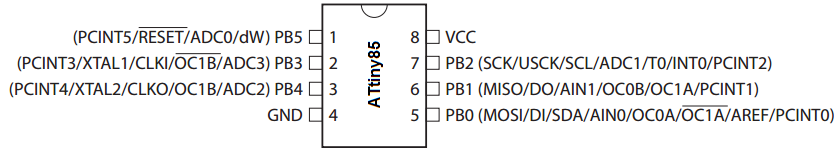
The power pins are VCC and GND, pins 8 and 4. Anywhere from 1.8V to 5.5V can power the ATtiny85 chip. To our circuit, we will simply apply 5V to VCC and connect GND to power ground.
Besides the 2 power pins discussed right above, the other 6 pins of the ATtiny8 are I/O pins labeled as PORTB pins. These are labeled on the datasheet and in the pinout above as PB0 to PB5.
These pins can be used as inputs or outputs, and they have various uses depending on what you need the pin for.
In our circuit, we are simply using the I/O pins or PORTB pins as outputs.
The PORTB pins of the ATtiny85 source power, so when connecting a digital output, the port provides positive power to the output device, so that we just need to connect the other end of the device to ground.
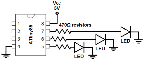
ATtiny85 LED Circuit
The circuit diagram of the LED circuit we will building with an ATtiny85 microcontroller is shown below.
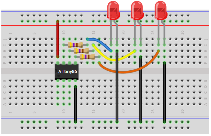
The breadboard schematic of the circuit above is shown below.
First, we give power to the ATtiny85 chip. This is done by connecting 5V to VCC, pin 8, and by connecting GND, pin 4, to ground.
Next, we attach to the outputs of the ATtiny85 microcontroller 3 LEDs. These LEDs are attached to outputs PB0, PB1, and PB2.
There are 3 more outputs avaiable on the ATtiny85, PB3, PB4, and PB5. However, we are only using the first 3 outputs, but you can easily extend it to all 6 outputs.
Being that the outputs source current, we connect the anode terminal of the LED directly to the output and the cathode end gets connected to ground. This supplies sufficient power to the LEDs. Being that LEDs only require about 10mA-20mA of current, they don't use that much power. However, for devices that need significantly more current such as a motor, for instance, we would have to connect a transistor to the output and then attach the output device to the collector of the transistor. This gives current amplification so that it can drive high-current devices. But, again, for LEDs, this is not necessary.
This establishes all the connections that are needed for this circuit.
Now all we need is the code.
Code
The code needed in order to turn all the LEDs on is shown below.
#include <avr/io.h>
int main(void)
{
while(1)
{
DDRB= 0xff;
PORTB= 0xff;
}
}
First, we must important the <avr/io.h> library.
Then we create the main loop() which will house the while(1) loop. This loop is an infinite loop. So the program will keep executing the code contained inside of it infinitely, over and over again. In this loop, we declare the DDRB pin as 0xff, which makes all of the I/O pins of the ATtiny85 outputs. In the next line, we set all the outputs HIGH, which turns the outputs on. Therefore, all 3 LEDs will turn on.
And this is a simple program to control output digital devices.
Related Resources
How to Build an LED Blinker Circuit with an ATtiny85 Microcontroller
How to Biuld a Traffic Light circuit with an ATtiny85 Microcontroller