AC Analysis of a Transistor Circuit: Mid Frequency Response
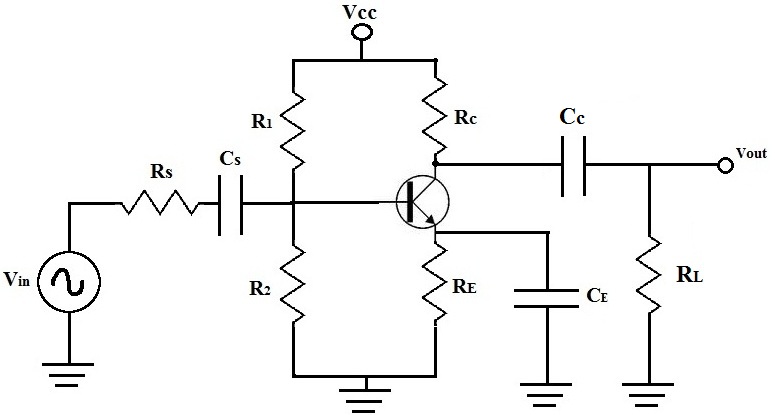
Above is a typical transistor circuit.
When analyzing a transistor circuit, different responses are produced by the transistor circuit depending on the frequency of the ac signals being input into the circuit. The frequency of the input signals is key to determining how the transistor circuit will respond. Depending on whether the input signals are of low frequency, mid frequency, or high frequency determines the transistor circuit's response to them. Here we will go over the mid frequency response of a transistor circuit.
AC Analysis
We will now perform AC analysis of the Mid Frequency Response of this transistor circuit to find its
Midband Gain.
When doing AC analysis of the mid frequency response of this transistor circuit,
-All external capacitors (Cs, Ce, and Cc) are shorted
-Internal capacitors are open
So there is no capacitive effect (capacitors) in midband
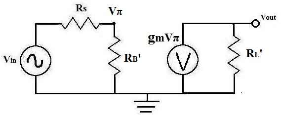
Below is the equivalent AC Equivalent Circuit of the schematic above for finding its midband:
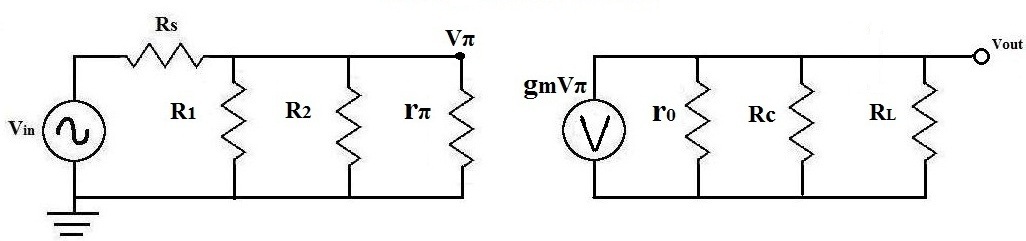
Analysis
Right away, we can begin doing analysis on the circuit to narrow it down and begin calculating values:
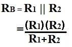
Solve R1||R2 (which is RB)
The first thing to do is solve for RB:
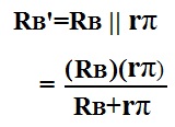
Solve for RB||rπ
Next, after you get the value for RB, solve for RB', which is RB||rπ:
Solve for Output Resistance RL'
Next, we solve for the output resistance of the transistor circuit, RL', which equal to r0 || Rc || RL.

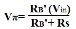
Solve for Vπ
Next, we solve for Vπ, which is the voltage that drops across rπ. This is important for other calculations in the AC
analysis.
Once we have these calculations, we can reduce the above circuit to the one below:
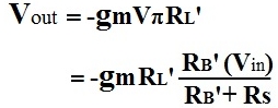
Now we can solve for Vout and then the gain of the transistor, Am:
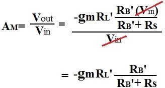
We now solve for the midband gain of the transistor circuit, Am:
The Midband Gain calculated in dB: