
How to Debug an Addr Flag Not Setting with the I2C Communication Protocol with an STM32 Microcontroller Board
In this article, we explain how to debug an addr flag not setting with the I2C communication protocol with an STM32 microcontroller board.
So before we go over how to debug this issue, let's discuss what exact this means.
So in order for 2 devices to be able to communicate with the I2C communication, they must have first physical connection. Then, in I2C communication, the master device must make communication with the slave device via the address of the slave device. This is how the master knows which device it is communicating with.
If the physical connection or the software doesn't have correct functionality, the addr flag will not set, and no communication can exist between the master and slave device.
So basically if the addr flag isn't setting, there is either a hardware connection issue or the right code isn't in place for the master to communicate with the slave at the given slave address.
The Addr flag in most (if not all) STM32 microcontroller boards are found in the I2C status register 1 (I2C_SR1).
This is shown in the diagram below.
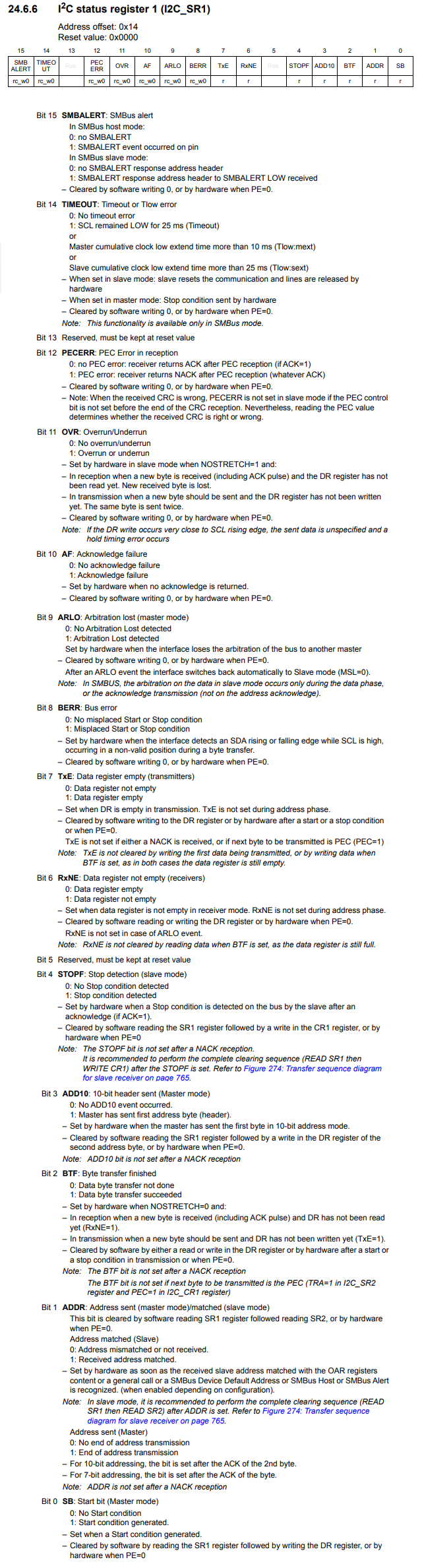
The Addr bit is bit 1.
It's a good idea to read the contents of this bit in the datasheet.
So this address bit is set when the address is sent by the master and matches the address of the slave device.
The slave device will then send an ACK signal, acknowledging that the master has made successful communication with it.
This is what, in turn, sets the bit HIGH. When the Addr bit goes HIGH, this signals that the received address matched (what the master sent out).
According to the datasheet, this bit is then cleared by software reading the SR1 register followed by reading the SR2.
So if you are running an I2C program and it gets stuck at the addr bit, meaning the addr bit isn't becoming a logic HIGH state, this means, essentially, that the 2 devices aren't making successful communication.
Thus, the addr bit will never go HIGH.
If the addr bit doesn't go HIGH, this means the master has not made successful communication with the slave.
If you debug your STM32 project by observing the SFRs,
you will see that the addr bit of the SR1 register never goes HIGH.
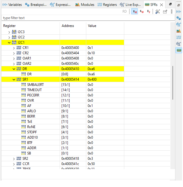
You can see that the addr bit of the I2C status register 2 is 0x00.
Why would this be the case?
Hardware Setup Issue
One of the first reasons this would be the case is there is a hardware issue.
If there is a fault in the hardware connection, I2C communication will not work.
This could be for many reasons.
One thing you should definitely do is read the datasheet to find out all the necessary connections for I2C communication.
Usually in datasheets, it tells you exactly what pins need to be connected to what for I2C communication.
Without the proper connections, I2C connection will fail and the master will never have successful communication with the slave device.
As an example, let's take the ADXL345 accelerometer.
This accelerometer can communicate with a master device via I2C or SPI communication, but the 2 communication protocols have different hardware setups.
Below is the hardware connections that are necessary for I2C communication.
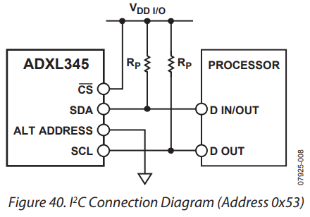
So it's very important to follow the datasheet when you are working with I2C circuits.
So in order to have I2C communication work, the CS (chip select) pin must be connect to HIGH voltage.
According to the datasheet for the ADXL345 accelerometer, I2C mode
is enabled if the
Another important hardware connection is that the SDA (data) and SCLK (clock) lines must be connected to VDD via external pull-up resistors. You cannot simply use the pull-up resistors in software, because their values are too high. You need to use external pull-up resistors, usually in the range of 2K-10K in value. The software pull-up resistors for STM32 boards are normally 40K in resistance, which is much too high to function. So make sure that this is done correctly.
A next important thing for proper hardware connection is the ALT Address pin.
Again, follow the datasheet for the instructions.
Normally, an I2C device has 2 addresses, an address and an alternative address.
This is done just in case the master has multiple slave devices on the bus that have conflicting addresses. In the case that 2 slave devices have the same address, one can be changed to a different address by using the alternative address instead.
According to the datasheet for the ADXL345 accelerometer, when the ALT Address pin is HIGH, the accelerometer is addressed with the address, 0x1D followed by the R/W bit. When the ALT address pin is LOW (tied to ground), the accelerometer is addressed with the alternative address, 0x53 followed by the R/W bit.
So you must use the right address for the hardware connection of the ALT address pin.
So this sums up the hardware connections.
Software Setup Issue
If your hardware is correct and you're confident of this, it can be a software.
Software issues are probably easier to debug, being that the STM32 software has so many debugging tools, but it can still be a challenge.
It's better just to follow already proven code for I2C and then just make the necessary adjustments for your I2C device, such as the address.
Below is the code for an I2C driver.
There are numerous things to take into account for the software setup for I2C communication.
The first is that you must set up the necessary pins to be in alternate function and use the designated pins set by the board manufacturer to function as the necessary I2C pins.
Another thing you must make sure to do is set the SDA and SCLK pins as open drain outputs. When working with I2C, the SDA and SCLK lines must always be set to open drain output configurations.
Optionally, you can enable pull-up resistors for the SDA and SCLK pins, but you must still connect external resistors from 2K-10K in value.
It is always good practice to reset the I2C communication through the SWRST (software reset) bit of the I2C control register 1. You must reset it and then take it out of reset.
The I2C1_byteRead() function is the function that establishes communication between the master and slave device.
This functions as an I2C driver, so all you would need to do is
modify the slave device address, and all should be well.
So this is how to debug an I2C program when the addr flag is not
setting with an STM32 board.
Related Resources