How to Convert an Arduino into an AVR Flash Programmer
In case you don't have an AVR programmer but you do have an arduino, the arduino can be converted into an AVR flash programmer, meaning it can program bare AVR microcontroller chips.
Say if you have an AVR chip and you want to program the chip, so that the program that you've written and compiled gets stored into the flash
memory of the chip to be executed. The arduino, with some specific wiring, can act as this flash programmer. This way, you won't need to spend extra dollars
on an AVR flash programmer.
Being that an arduino has all the hardware onboard to upload and run programs on Atmel AVR chips, it is all that surprising that it can function as an AVR programmer itself. In this case, it doesn't actually execute the program. It just transfers the data from the computer to the AVR chip that you want to program.
Using an arduino is especially easy, because one real advantage of the arduino is that the chip on it comes pre-flashed with a bootloader, which is code that enables teh chip to communicate with your computer over the serial line in order to flash program itself. A second advantage is that an arduino comes with a built-in USB-to-serial converter, so you can just use the USB cable to establish connection with the computer.
And using the arduino as a hardware programmer is pretty easy. With just 6 wires between the Arduino and the AVR chip, we give the AVR chip a source of power and a flash programmer that is just as good as any other type of AVR flash programmer.
So how do we do this?
The first step toward using the arduino as a flash programmer is hooking up the necessary hardware of the arduino board to the AVR chip.
Before we actually show the schematic, it would help tremendously to know the pinout of an Atmel AVR chip. Specifically here, we will look at the pinout of a very common AVR chip, the Atmega168. The Atmega328, also very popular, follows the same pinout. It's just a chip that contains more memory.
Below is the pinout of the Atmega168/Atmega328:
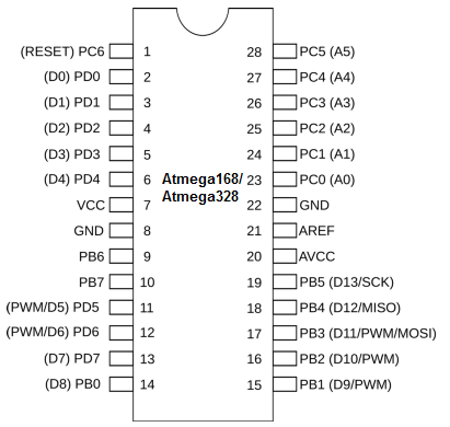
Knowing the pinout of the Atmega chip is very important, so that you can know which pins you are connecting to on the Atmega chip and why
you are connecting there. Else, you will be connecting blindly to pins, not even knowing which pins they are.
Circuit Schematic
The hardware schematic of the arduino pins connected to the Atmega168 pins is shown below:
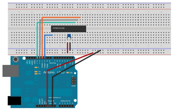
So, in total, these are the 6 connections that need to be made.
The table below summarizes these connections:
| Connections of Arduino to Atega168/328 | |
| Arduino pin | Atmega168/328 Pin |
| 5V | Pin 7 (Vcc) |
| GND | Pin 8 (GND) |
| 10 | Pin 1 (RESET) |
| 11 | Pin 17 (PWM) |
| 12 | Pin 18 (MISO) |
| 13 | Pin 19 (SCK) |
The essential 6 connections are power, ground, RESET/PC6, SCK/PB5, MISO/PB4, and MOSI/PB3.
We give power to the Atmega168 chip by the 5V terminal and GND terminal of the arduino. Pins 7 and 8 on the Atmega chip represent Vcc and GND. These are the pins we supply voltage to in order to give power to the Atmega168 chip. In between Vcc and GND, we have placed a 100nF (0.1µF) capacitor. This capacitor is simply to filter out any noise that may be on the DC power line, so that we can get a clean DC voltage signal.
Once we have the power, we make the other 4 connections that are needed.
Digital D10 pin of the arduino connects to pin 1, the RESET pin, of the Atmega168 chip. This is a very important connection. AVR microcontrollers are able to write into their own flash program memory space when you reset them. All of the Atmega series microcontrollers are set up so that when you reset them, they start listening for data on the SPI lines and with the right instructions can program themselves. A flash programmer works by grounding the RESET line, which halts the CPU and signals the AVR to start listening on the SPI bus. The programming instructions (of the program to be executed) can then be transmitted over the SPI bus. After each instruction or section of code, the AVR writes the received data to flash memory. Some of the tiny AVR chips flash the data to program memory after every few bytes, which can be slow. Larger and newer chips store the incoming data in a temporary page memory and then write it all at once, which is much faster. After the programming is complete, the data from the flash memory can be read back out of the AVR's flash memory to verify that it's correct. AVRDUDE, which we will introduce later, can do this.
The other 3 connections are Arduino pin D11 connecting to Pin 17 on the Atmega168 chip. D12 connecting to pin 18. And D13 connecting to Pin 19.
Once we have these connections, this completes the arduino as a flash programmer. With the compiled software code, we can use this Arduino flash programmer to
transmit the compiled program to the AVR microcontroller's flash memory to be stored. With the program stored in flash memory, it can be executed by the AVR
microcontroller.
We can attach status LEDs to the above Arduino flash programmer, so that we can physically see the status of what is going on when we run a program.
Below is the circuit schematic diagram of the Arduino flash programmer with status LEDs connected:
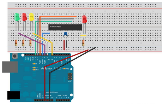
The three LEDs to the left are status LEDs. The green LED will pulse while the ArduinoISP is waiting for input. The yellow LED will light when
data is being transferred from the arduino to the AVR, and the red LED will light up if there is an error. Again, these LEDs are optional, but they give you
the ability to visually check what is going on when you are programming the flash memory of an AVR. Being that these are LEDs, we must attach resistors in order
to limit current to them, so that they don't blow out. The resistor values aren't critical. Anything above 200Ω will suffice. Being that the LEDs are given
5V of power
and their threshold voltage is normally about 1.7V and they are rated for about 20mA, 200Ω is around a good value, since (5V-1.7V)/200Ω= 16.5mA.
Next, we'll show the actual programming of an AVR chip, such as the Atmega168/328, in which we program the AVR to blink an LED. This is a circuit
in which the bare AVR chip is used, not an arduino. As soon as the page of this project is up, the link will be posted here.