How to Build a Real-time Clock Circuit with an Arduino
In this project, we are going to build a real-time clock circuit and connect to an arduino microcontroller.
A real-time clock, or RTC, is an integrated circuit that keeps track of current time. It can keep track of seconds, minutes, hours, days, weeks, months, and years with leap year capability. It can be operated in 12-hour or 24-hour format.
Real-time clocks are used in electronics where time needs to be always known at all times ongoing or during any time-sensitive or time-critical applications.
Real-time clocks normally have batteries attached to them that have very long life. Therefore, the batteries last a very long time, several years. The battery keeps the RTC operating, even when there is no power to the microcontroller that is connected up to. So even if the arduino powers off, the RTC can keep operating due to its battery. Therefore, it can always keep track of the current time and have accurate time.
Therefore, learning about them, how to connect them to microcontrollers, and how to program them is very useful.
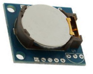
The RTC module we will use in this circuit contains the DS1307 chip.
Components
- DS1307 RTC Module
- Arduino
The DS1307 is a real-time clock chip which can count seconds, minutes, hours, date of the month, month, day of the week, and year with leap-year compensation.
It's a great clock that can always keep track of time regardless of whether the microcontroller it connects to is powered on or off. This means if you shut off the microcontroller, the chip will still keep track of time ongoing. A microcontroller, on the other hand, without a real-time clock chip, will restart time to back to the beginning 0 everything it's powered off. With RTCs, with critical or time-sensitive applications, we can always keep a precise record of time.
The RTC module, depending on which one you use, either has 4 or 5 pins. Usually, the pins are VCC, GND, SDA, SCL, and SQW. Some modules may not have SQW but some do. All are explained in detail below.
VCCis the positive power voltage supply. VCC should be about 5V. When VCC is supplied a voltage above the battery's voltage, the chip will function off of VCC. The battery is only used when VCC falls below Vbat, the battery contained on the RTC module board. Since the arduino supplies about 5V of power, it is perfect for powering the RTC module board.
GND is power ground. This terminal on the RTC board connects to the GND terminal on the arduino.
SDA is the serial data line. It's the line that transmits the time from the RTC chip to the microcontroller it's connected to. Therefore, the microcontroller can output the correct time at a given time. The SDA terminal connects to analog pin 4 on the arduino.
SCL the serial clock line. The serial clock line is needed to synchronized data movement on the serial interface. The SCL terminal connects to analog pin 5 on the arduino.
SQW is the square wave/output driver (SQW). This allows us
to change the square wave frequencies to either (1Hz, 4KHz, 8KHz, or 32KHz). For our basic
application, we will not be adjusting the square wave frequency, so we leave
the pin unconnected.
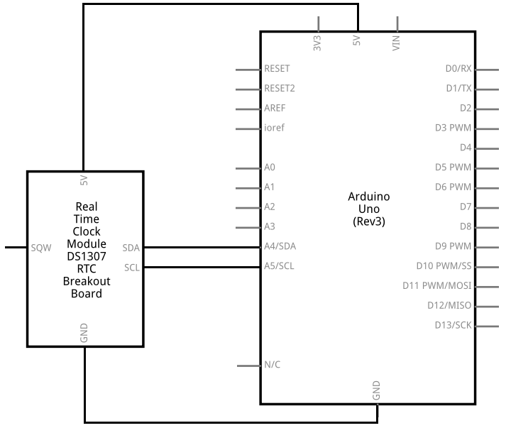
Arduino Real-time Clock Circuit
The real-time clock circuit we will build with an Arduino is shown below.
This above circuit built on a breadboard is shown below.
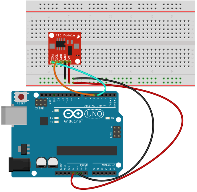
The physical connections in this circuit are pretty straightforward. Power established to the RTC module board. And then the data line (SDA) and the clock line (SCL) are connected to analog terminal pins 4 and 5.
With these connections, we have all the hardware connections. Now all we need is the software to get this circuit operating.
Code
The code needed to display the time that is currently recorded by the real-time clock module.
#include <Time.h>
#include <Wire.h>
#include <DS1307RTC.h>
void setup() {
Serial.begin(9600);
setSyncProvider(RTC.get);
if(timeStatus()!= timeSet)
Serial.println("Unable to sync with the RTC");
else
Serial.println("RTC has set the system time");
}
void loop()
{
if(Serial.available())
{
time_t t= processSyncMessage();
if (t > 0)
{
RTC.set(t);
}
}
digitalClockDisplay();
delay(1000);
}
void digitalClockDisplay(){
Serial.print(hour());
printDigits(minute());
printDigits(second());
Serial.print(" ");
Serial.print(day());
Serial.print(" ");
Serial.print(month());
Serial.print(" ");
Serial.print(year());
Serial.println();
}
void printDigits(int digits) {
Serial.print(":");
if (digits < 10)
Serial.print('0');
Serial.print(digits);
}
#define TIME_MSG_LEN 11
#define TIME_HEADER 'T'
time_t processSyncMessage() {
while(Serial.available() >= TIME_MSG_LEN) {
char c= Serial.read();
Serial.print(c);
if (c == TIME_HEADER) {
time_t pctime=0;
for (int i=0; i < TIME_MSG_LEN -1; i++) {
c= Serial.read();
if (c >= '0' && c <= '9') {
pctime= (10 * pctime) + (c - '0');
}
}
return pctime;
}
}
return 0;
}
This is the code needed to give the time from the RTC. It gives the hour, minute,
second, month, and year.
Related Resources
How to Build a Real-time Clock Circuit with a DS1307 Chip