
How to Build a Soil Moisture Sensor Circuit with an Arduino
In this project, we are going to build a soil moisture sensor with an Arduino microcontroller.
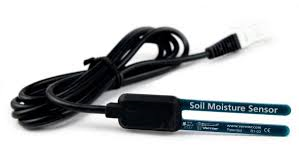
A soil moisture sensor, also called a hygrometer, measures the amount of moisture, or water, in the soil.
Therefore, we can tell whether the soil has enough moisture or not. So it is a good diagnostic tool for caring for plants of all types.
If the soil is extremely dry, then you will know the plant should be watered.
If the soil is very moist, then you will know that it does not need to be watered.
The soil moisture sensor we will build is simple to connect because we're going to use a prebuilt module. This means everything is already included. We simply have to connect the output terminals to a microcontroller such as the Arduino.
If you type in 'Arduino Soil Moisture Sensor' into ebay, you will see the complete type of sensor needed to build this circuit.
The sensor has 4 terminals for connection, Vcc (for power), GND, Analog output, and Digital output.
Vcc and ground are how the sensor gets the power it needs to operate. Here we connect 3.3V-5V of external power.
Analog output shows the value the sensor is reading which correlates to the amount of moisture it detects. The analog value varies from 0 (very wet) to 1023 (very dry). So if the soil is very dry, the analog output will have a very high reading. If the soil is we, the analog output will have a very low reading. This is how we will know whether the moisture content of the soil.
The Digital output simply goes high or low. Since we are working with a microcontroller that can interpret analog signals, this is more precise than digital signals, so we will not connect the DO pin. If we weren't using a microcontroller, then we probably would have to use DO instead of AO.
A soil moisture sensor, again, is a very useful tool for plant care and maintenance.
Components
- Soil Moisture Sensor Module
- LED
- Arduino
The soil moisture module has 4 pins.
The table below summarizes these pin connections.
| Soil
Moisture Sensor Terminals |
Arduino Terminals |
| Vcc | Connects to 5V terminal |
| GND | Connects to GND terminal |
| AO | Connects to an analog terminal (A0-A5) |
| DO | Unconnected |
Arduino Soil Moisture Sensor Circuit
The arduino soil moisture sensor circuit we will build to read the moisture of soil is shown below.
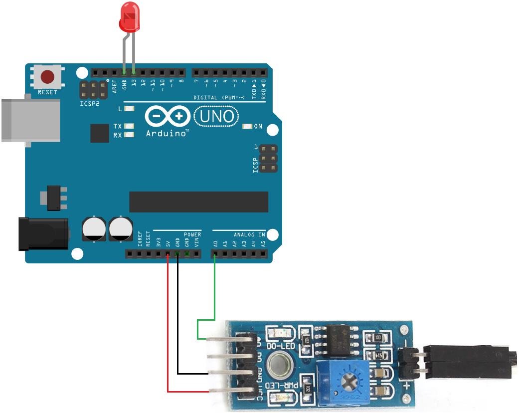
This soil moisture sensor circuit is pretty simple.
We connect Vcc to 5V on the arduino board and GND to GND on the arduino. This establishes power for the sensor.
We then connect AO to A0 on the arduino board. This connects the sensor to an analog terminal on the arduino. The arduino can read the value from the sensor and output this value to us.
The analog terminals of an arduino have a built-in analog-to-digital converter, which can read analog values and convert them into digital signals, which the microcontroller can interpret.
Next all we need is the code.
Code
This is the code necessary to run this soil moisture sensor.
const int LED= 13;
void setup(){
Serial.begin(9600);
pinMode(LED,OUTPUT);
}
void loop() {
int sensorReading= analogRead(A0);
Serial.println (sensorReading);
if (sensorReading > 800){
digitalWrite(LED,HIGH);
delay(1000);
digitalWrite(LED,LOW);
delay(1000);
}
}
This soil moisture sensor flickers the red LED when conditions get very dry, a sensor reading above 800.
You don't have to have this. You can take out the LED and have a pure sensor if you want. The point is that this circuit really alerts us to dry conditons and if the plant needs
watering. There are many modifications you can make, including having a buzzer sound or anything.
Related Resources
How to Build a Dark-activated Switch