How to Build a Simple Attenuator Circuit
An attenuator circuit is a circuit which attenuates, or decreases the strength of, a signal.
In this project, we will build a very simple attenuator circuit using nothing but a resistor or potentiometer coupled with our circuit.
Attenuator circuits are very useful for whenever we need to decrease the strength of signals. Think of applications such as volume control. If the music is too loud, then we need to attenuate them in order to get less volume. The music comes to our ears through audio signals. We then would need an attenuator to decrease the level of these audio signals, which translates into decreased volume. Another application is for oscilloscopes. If we are looking at a very large signal which we want to scale down, an oscilloscope must have an attenuator inside to be able to do this. Basically, attenuators are useful in all applications in which we need to decrease the signal strength of signals.
The attenuator we will build is an absolutely simple, yet effective, circuit for attenuating signals so that we can decrease the level of a signal.
The parts we will use to build this circuit are:
Components Needed
- 10KΩ Resistor or Potentiometer
- Power Source
- Jumper wires
For this circuit, we can use a resistor or potentiometer to act as the attenuator. A resistor will act as a fixed attenuator, while a potentiometer will act as an adjustable attenuator. Since being adjustable allows for greater flexibility in the levels of attenuation, we will in this project build an adjustable attenuator. However, if you only have resistors, use a resistor and keep swapping them out to see which gives the attenuation you want.
For this circuit, we will use a 10KΩ potentiometer.
There are 2 types of potentiometers, linear and log taper potentiometers. Linear potentiometers are potentiometers which change resistance in a linear fashion. This means that, for example, if we turn the potentiometer knob 20%, the resistance will change 20%. It's a perfectly direct relationship. Log taper potentiometers are potentiometers which change resistance in a parabolic fashion. Unlike linear pots, log tapers do not change linearly. They change parabolically because our ears perceive sound in a logarithmic fashion. If we were to use a linear potentiometer for volume control, increasing or decreasing sound, the volume changes would turn out right. A linear potentiometer's adjustment grows far too rapidly as the pot is turned up from zero. Thus, it is not good for volume changes. Thus, log, or rather, audio, tapers are used for volume control.
The type of potentiometer we use, linear or log taper, depends on the application we are using it for.
So we would use linear potentiometers for pretty much all applications besides audio. But for audio, we would use log taper, or audio taper, potentiometers.
So if you are using this circuit to decrease audio signals, use a log taper pot. But for all other uses, just use a regular linear
pot.
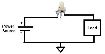
Attenuator Circuit Schematic Diagram
The circuit we will build is shown below:
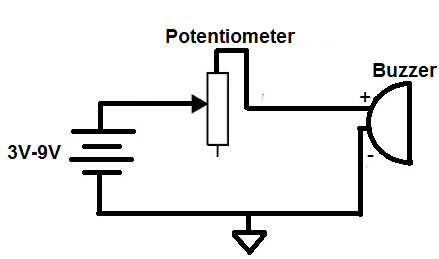
Here we are using the potentiometer as an attenuator for the buzzer sounds.
Because this is for audio sounds, the best potentiometer to use is a log taper or audio potentiometer.
However, if you do not have a audio taper pot, then use a load that does not deal with audio, such as a DC motor or a fan. For these applications, a linear potentiometer will be used.
Whichever pot or circuit you use, start the potentiometer with its resistance all the way to the lowest value which is near 0Ω. Then slowly turn the potentiometer so that its resistance decreases. With the buzzer, you will notice that the sounds grows lower and lower and lower until it cannot be heard anymore. With a DC motor, the motor will spin slower and slower until it stops. With the fan, it will spin slower and slower. And this is how an attenuator works.
This circuit demonstrates the most basic type of attenuator that exists.
Related Resources
Types of Diodes
What is a Varactor?
What is a Protection Diode?
What is a Photodiode?
What is a Shockley Diode?
What is a Fast Recovery Diode?