
C Structure Code of thes RCC Register Map of an STM32F407xx Microcontroller Board

In this article, we show the C structure code of the RCC register map of an STM32F407xx microcontroller board, so that we can reference each of the RCC registers.
We then will be able to reference each of the peripheral clocks of the STM32F407xx microcontroller, so that we can do things such as enable or disable a specific components on a specific bus.
This code can go into the device specific header file.
Instead of looking up the address of each of the RCC registers in order to reference them, you can create a C structure that contains all of the RCC registers.
This is the best practice way of referencing elements in an STM32 board.
Below is the RCC register map of the STM32F407xx board.
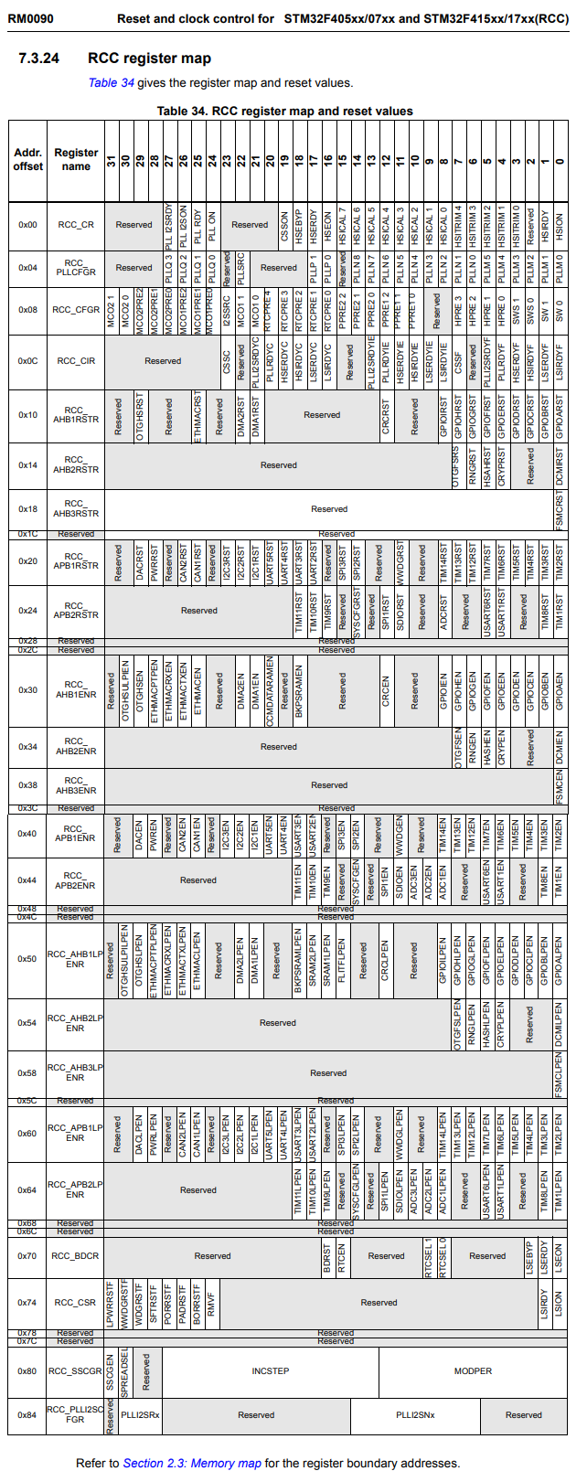
So you can see it has quite a number of registers, many of which we may have to reference in order to initialize values for any of the various programs that we write.
Instead of looking up all of the addresses for each of these registers and manually assigning these addresses to variables we create, we can instead create a C structure that contains all of the RCC registers.
We do this in the C code below.
What you want to do is you want to create a separate header file and it's good practice to name this file by the STM32 board you are working with. For example, if I am working with the STM32F407xx board, I can name this file, stm32f407xx.h
Inside of this file, I will put the C structure that contains all of the RCC registers.
Below is the contents of the stm32f407xx.h file.
So let's now go over the code.
So first we create a C macro, which contain the base address of the RCC registers.
As best practice, you want all of these registers to be volatile, as they may be subject to frequent change within a program. All of these registers are 32-bit registers, so we initialize them with uint32_t.
As you can see, we follow the RCC register map. You must put everything in order, as is displayed in the memory map.
The first register of the RCC port registers is the CR register (control register). This has an address offset of 0x00. This register must come first or else the structure will be wrong.
The second register is the PLLCFGR register, or the RCC PLL configuration register. This register has an address offset of 0x04. This register must come next, as order is vital for a C structure representing registers.
The third register is the CFGR register, or the RCC clock configuration register. This register has an address offset of 0x08.
Notice how each subsequent register increases by an address offset of 4. This is because each register is composed of 4 bytes (32-bit registers).
You can know which register is next by the increment of 0x04 in the address offset.
So this continues in our program all the way down to the register, DCKCFGR2.
We refer to this C structure as, RCC_RegDef_t
This is a fitting name, because it forms the register definition for each of the RCC registers.
(RCC_RegDef_t*) represents the pointer to this general structure we created. We then have to initialize each of this definition to the base address of the RCC registers.
This is done through the following line, RCC_RegDef_t *pRCC= ((RCC_RegDef_t*)RCC_BASEADDR);
Now we can use this pRCC pointer variable in our C program to be able to reference any of the RCC registers.
Next we have the line, #define RCC ((RCC_RegDef_t*)RCC_BASEADDR)
This just allows us to have a macro version of the RCC pointer variable.
We are now finished creating our C structure.
Now we can go to our main C program and now use this structure that we have created.
The code below is an example of this.
So one of the most important things is you must include the header file at the top of the C program. Otherwise, the C structure you created will not be tied in with your program.
If it states that the file is not found, then you must include the path for it, so that it can be found.
We then have our main function.
We now can reference any of the RCC registers and set set any register equal to any value as we need to for our program to work.
In this code in this example, we turn on the peripheral clock for GPIO port A and USART1.
So this is the C structure code of the RCC register map of an STM32F407xx microcontroller board.
Related Resources