
Current Sensor Circuit with an External Amplifier Calculator
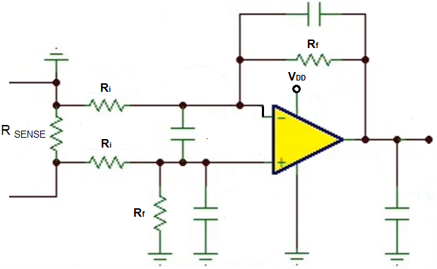
This current sensor circuit with an external amplifier calculator calculates the VSENSE, gain required for amplification, and the input resistor, Ri, and the feedback resistor, Rf.
This type of circuit is used for battery management systems to monitor current to check for things such as overcurrent to ensure safety of the system.
VSENSE is the voltage that falls across the currense sense resistor, or the shunt resistor. The current sense resistor is a small, precise resistor that allows us to measure current. Because it is so precise, it can give us an accurate reading of the current across it. This resistor value is very small, in the order of a few milliohms. Therefore, when current flows through it, it produces a voltage output of millivolts, which is why it needs an external amplifier to amplify it to the range that the ADC deals with. VSENSE is vital to calculate because in order to calculate the current flowing through a battery management system, we cannot measure the current directly. ADC chips cannot measure current, but only voltage. Therefore, in order to measure current, we must measure the voltage across the current sense resistor, which is VSENSE, and then use ohm's law to calculate the current, which is I= V/R. However, because the output voltage is so small due to the resistor value being so small, we amplify first and then we can have a microcontroller do all the math to know what the original current is flowing through the BMS; this again allows us to monitor current in our BMS to ensure it's efficient and safe and appropriate for the system.
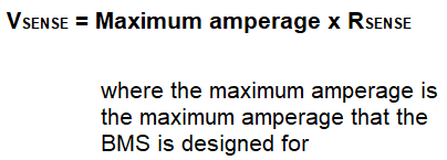
We calculate the maximum VSENSE by using ohm's law and the maximum current conditions for which the battery management system was created. So if the BMS was designed to handle a maximum current condition of 62.5A, then we know this is maximum conditions. In this case, the maximum voltage that would fall across the current sense resistor would occur when the maximum current passes through the current sense resistor. If for the system this is 62.5A and the current sense resistor is 0.0005Ω, the the maximum voltage that will fall across the current sense resistor is, V= IR= (62.5A)(0.0005Ω)= 0.03125V. 0.03125V is the maximum voltage that will fall across the current sense resistor when the current is at the system's maximum conditions.
But, again, this voltage is very small. If 0.03125V is the maximum voltage when 62.5A, then much smaller voltages occur when the current is less than 62.5A. For example, at 31.25A of current passing through the system, the voltage across the current sense resistor will be 0.015625V. At 15.625A passing through the system, there will be a voltage drop of 0.0078125V across the current sense resistor. These were all given to show that these voltages are way too small for the ADC to work with. ADCs typically work with voltages on a scale from 0V-5V. Therefore, instead of working with these voltages, we need to amplify them to get to the volts range instead of the millivolts range.
So, again, the maximum voltage across the current sense resistor is 0.03125V when the maximum amperage conditions is 62.5A for a 0.0005Ω current sense resistor. If we are working with an ADC that has a maximum voltage of 5V, meaning it can read voltages up to 5V, we want to convert the maximum voltage across the current sense resistor (for example, 0.03125V) to the maximum voltage that the ADC can read (for example, 5V). The process of converting the current sense resistor voltage to the maximum ADC voltage is the gain required for amplification.
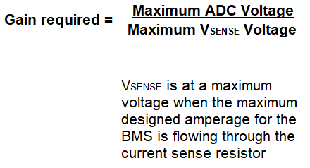
The gain required for amplification is determined by the formula, Gain= Maximum ADC Voltage/Maximum Current Resistor Voltage.
In the case of a 0.0005Ω current sense resistor with 62.5A passing through it, this produces a voltage drop of 0.01325V. If working with a ADC that has a range of 0V-5V, the gain required would be, Gain= 5V/0.01325V= 160.
In order to amplify the maximum voltage drop across the current sense resistor to the maximum ADC voltage, an amplification of 160 is needed.
The last thing we need to find is the value of the input and feedback resistors, which gives the gain for the op amp circuit.
The formula for the gain of an op amp is, Gain= 1 + Rf/Ri.
Therefore, in this example, Rf/Ri needs to be 159, or stated otherwise, Rf needs to be 159 times greater than the value of Ri.
So this circuit works with various generic op amps to produce the amplification needed for a current sensor circuit for a battery management system.
With the value of the current sense resistor, RSENSE, the maximum current that the BMS can handle, and the maximum ADC voltage that the microcontroller that will be managing your BMS can read, we can determine VSENSE, the gain required for amplification, and the input and feedback resistors for the op amp circuit.
This allows us to give proper amplification to a current sensor circuit for a BMS, whose output we can then connect to a microcontroller for reading and management of the battery management system.
Related Resources