
How to Build a Current Sensor Circuit with an External Amplifier for a BMS

In this article, we show how to build a current sensor circuit with an external amplifier for a BMS.
So it is important in battery management systems to monitor current to see if the current levels are safe and effective for operation. Monitoring current can help us to detect overcurrent conditions, which is important for the safety of the system.
One very popular method of sensing current is by using a resistive shunt. This is a very small precise resistor. The reason it needs to be precise is we want a precise current reading from it. In order to sense current, we don't measure the current directly. Instead, we measure the voltage. From the voltage reading, we can calculate the current using ohm's law, I= V/R. This is how we can know how much current is flowing through the system. Since the resistor is very small in value, in the milliohms (mOhms), the voltage across it will be very small. Therefore, in order for an IC to read this voltage, it first needs to be amplified. Most ICs will not read millivolts. Instead, we amplify it up using amplification and then we're able to calculate the current through math and the amplification factor that was used. We go through all these calculations below.
There are 2 methods of approaching current sensor circuits for systems such as battery management systems depending on the IC you are working with.
If you are working with an IC that already has internal circuitry inside of it that provides amplification, you may not need to create your own external amplification circuit, as amplification is already provided by the IC.
If you working with an IC that provides no amplification, then you will have to create your own external amplification circuit using a chip such as an operational amplifier.
In this article, we show how to create a current sensor circuit with an external amplifier.
We use a general operational amplifier, the MCP6022, which is a dual operational amplifier.
The datasheet for the MCP6022 operational amplifier is shown at the following link: MCP6022 Operational Amplifier Datasheet.
The pinout for the MCP6022 amplifier is shown below.
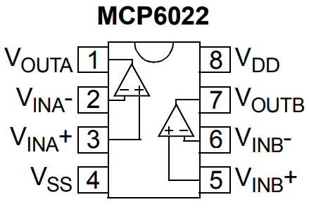
As stated before, the MCP6022 is a dual operational amplifier, meaning it has 2 op amps inside of the chip.
For our circuit, we are only using one op amp.
So the second op amp is completely unused, so we don't make any connections to pins 5, 6 and 7.
Pins 4 and 5 are the power pins to give power to the chip. The chip is powered by 5VDC. Pin 4 is ground. Pin 8 is the supply voltage, which we feed +5V.
So the next consideration we have for our circuit is our calculations.
So we'll do the calculations right now.
As explained before, this amplifier circuit amplifies the output from the current sensor circuit, so that we can read the value.
The next thing you have to know about your battery management system is how many amps was it designed to manage; this is the maximum amount of current that the battery management system is designed to manage.
This is important because the maximum current through the BMS translates to the maximum voltage, which for the MCP6022 ADC is 5V. So if the maximum current, 62.5A is flowing through the battery management system, this translates into a voltage reading on the MCP6022 chip as 5V. If the current flowing through the BMS is half, about 31.25A, this translates into a voltage reading of 2.5V from the IC. If the current flowing through the BMS is 10A, this translates into a voltage reading of 0.8V.
So the output of the op amp can be anything from 0V to 5V. 0V would mean the current is 0A, while 5V would mean the current is 62.5A.
So when dealing with an op amp, you will need resistors in order to set the gain for the op amp.
So, as stated before, we need to make the maximum amperage which is 62.5A equivalent to an output from the op amp of 5V, which is the maximum voltage from 0V-5V range.
Let's say that the maximum amperage of 62.5A flows through the current sensor resistor which is 0.0005Ω, this gives a voltage of V= IR= (62.5A)(0.0005Ω)= 0.031V.
So 0.031V is the maximum voltage that the current sense resistor will have over it in maximum. Therefore, we want to translate this into the maximum ADC voltage of 5V.
The formula for the gain requirement, is (Maximum_ADC_Voltage)/(Maximum_Current_Sensor_Resistor_Voltage)= 5V/0.031V≈ 161
So this means the op amp needs a gain of 161.
With a gain of 161, the maximum amperage of 62.5A flowing through the current sense resistor will produce an output voltage from the op amp of 5V, which is the maximum voltage.
The gain of the op amp circuit we will build is op_amp_gain= 1 + Rf/Ri
Therefore, we need to select an output resistor that is 160 times the value of the input resistor.
So if we select the input resistor, Ri to be 100Ω, then the output resistor needs to be 16KΩ.
The op amp circuit we will build is shown below.
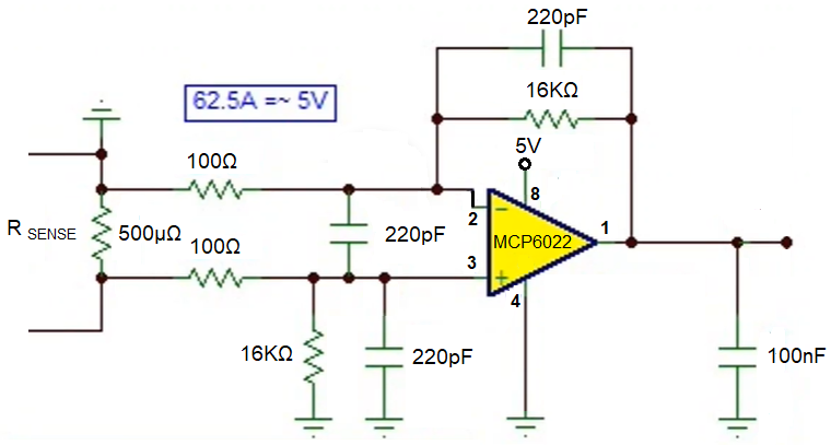
So this circuit is a rugged and proven circuit for current sense resistor circuits.
Notice that the input resistor is 100Ω and the output resistor is 16KΩ; this gives us a gain of 161.
The capacitors are for 220pF capacitors are for filtering.
The 100nF capacitor at the output is also for filtering.
So now you connect the output of this op amp, which is pin 1 to the input
of the IC that will read this voltage and controls the battery management system.
And this is a current sensor circuit that uses an external amplifier,
whose output can then be connected to the microcontroller which controls the battery
management system.
Related Resources