
Device Tree Parent and Child Node Representation in Linux- Explained
An important concept to know about device tree files are the representation of parent and child nodes.
Parent and child nodes are important because they represent hardware as it exists on a board.
Let's take the example of a bus, which could represent a parent node.
On this bus are connected devices, which could represent child nodes.
Let's use a specific example on a real-life board.
Let's take the example of the AM335x bone common board.
To the I2C0 bus are connected the TPS chip and the baseboard_eeprom chip.
The I2C0 bus would be the parent node.
Since the TPS chip and baseboard_eeprom chip are connected to this bus, they would be child nodes.
So how would this be represented in code?
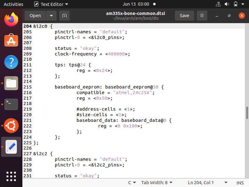
So if we look at this real-world example in actual code in the am335x-bone-common.dtsi file, we can see that the parent node is &i2c0 and the child nodes are tps and baseboard_eeprom.
The general format for parent and child nodes are shown below.
So you can see the parent node starts with an ampersand & and then there is a opening bracket {
The parent node encompasses all the child nodes. To finish it, at the very bottom, there is a closing bracket with a semicolon };
Each child node as has a label followed by a colon followed by the name of the child node. Each child node's name will have an @ symbol followed by the address. It is also convention when working with child nodes that if there is no address, it is convention just to start with @0 followed by incremental values of 1, i.e, @1, @2, @3, etc.
This is shown below.
You can see the sequential ordering from 0 to 3 above.
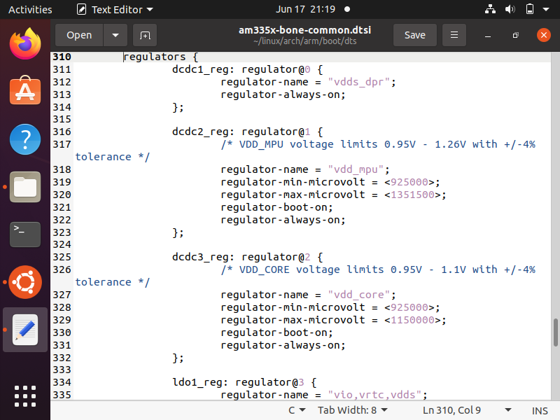
Below is the continuation of tese device nodes.
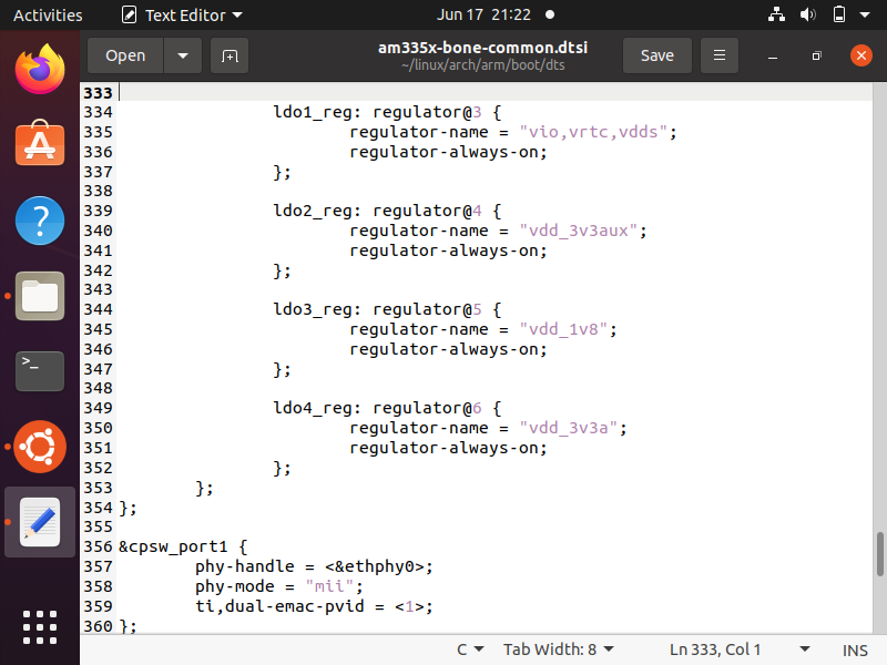
So you see that each device node has a label, a node name, and a device name (in this case regulator-name).
It's worth mentioning that when you have a series of child nodes that are related you can give them a common name, which above you can see is, regulators { }
In this case, the general format for parent and child nodes would be that as shown below.
So when working with a parent node that references its child nodes through addressing, such as the I2C microcontroller protocol, the child node name should be @ followed by the I2C address.
This is shown below.
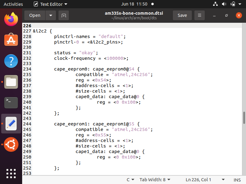
The continuation of this I2C2 child nodes is shown below.
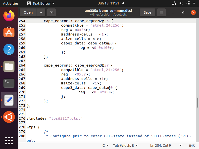
You can see how the address @ must be the same as as the reg property. This is the I2C address by which the I2C protocol addresses its child nodes. This is the register addresses of the child device.
The other bus protocols that do not use address numbering to address its child nodes can use a sequential numbering from 0 to the number of nodes to address its child nodes.
So this is how device tree parent and child node representation is done in linux.
Related Resources