
How to Build a Dual Full Battery and Low Battery LED Circuit
In this circuit, we will build a dual full battery and low battery LED circuit.
This is a circuit that will tell us, through LEDs, when the battery is at full strength (green LED will be on) and when the battery is near its dying stage (a red LED will be on).
You can choose these values to fit the battery that you have.
In our example, just for demonstration purposes, any voltage above 4V indicates that the battery is at full health. When it goes below this, the green LED (indicating full health) goes out. When the battery voltage then goes below 2.4V, then the red low battery warning LED goes on, indicating that the battery is low.
To do this circuit, we simply use a dual op amp chip, which is a chip that contains 2 op amps that we can use to compare the voltage differences. Because we have 2 LEDs, we need 2 op amps.
Apart from that, we just exploit the op amps to be able to compare voltages.
For the low battery warning LED (red LED), we just have to use an op amp to monitor when the voltage goes below 2.4V. When this happens, the red LED turns on.
For the full battery life LED (green LED), we have to use an op amp to monitor when the voltage is above 4V. As long as the battery voltage is above 4V, the green LED will be on.
Below is a list of all the components we use to build this circuit.
Components Needed
- LM393 Comparator Chip
- 2.4V zener diode
- 4V zener diode
- 2 1KΩ resistors
- Red LED
- Green LED
- 2 220Ω resistors
So all we need is the LM393 comparator chip and a few external components, which includes the 2 zener diodes, 2 LEDs, and 4 resistors.
The circuit that we will build that allows us to detect when the battery voltage is above 4V and when it goes below 2.4V is shown below.
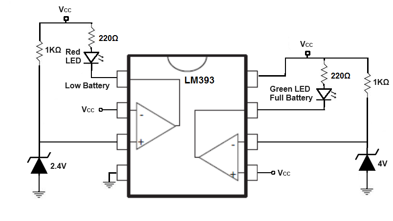
Pin 4 is GND and, thus, gets connected to the ground of the power source.
Pin 8 is where you connect the positive terminal of the power source. In this case, we are working with 5V. If you have a different voltage, you can use this but take note of the other voltages you will be working with, particularly with the zener diode voltage ratings.
The remaining 6 pins are the op amp input terminals and output terminals.
We will start with the red low battery warning LED.
Pin 2 is the inverting input terminal of the op amp. To this pin, we connect the 2.4V zener diode. This sets the voltage at this pin to a stable, regulated 2.4V. When working with op amps, you need to set a reference voltage. With this set reference voltage, you can then build the circuit so that a device such as an LED turns on or off above or below this reference voltage, depending on the circuit configuration. In this case, we make the circuit so that the red LED turns on when the VCC, which is the voltage from the power supply, is less than 2.4V.
Pin 3 is the noninverting op amp input pin. To this pin, we connect the device's power to. This pin connects to VCC, which represents the power source of the electronic device.
How the circuit works is that when the voltage at the inverting terminal is less than the voltage at the noninverting terminal, the corresponding LED for the op amp turns on.
So when the power supply voltage, VCC, drops below 2.4V, the red LED turns on, indicating that the battery life is low.
Now let's go on to the other LED, the green LED which indicates full battery health. In this case, it indicates when the battery is above 4V.
So in this setup, it's in reverse. Because we want the LED to be on when the voltage is above a certain voltage (rather than below it which is the case with the other LED), we place the battery voltage, VCC at the noninverting terminal and we set the reference voltage at the inverting terminal at 4V with the zener diode.
Remember that the op amp LED output will be HIGH when the voltage at the inverting terminal is less than at the noninverting terminal.
Thus, the LED will be as long as the battery voltage is above 4V. After the battery voltage drops below 4V, the LED will turn off, indicating that the battery is no longer at full health.
Pin 5 is the noninverting terminal.
Pin 6 is the inverting terminal.
Pin 7 is the output of the op amp, where the LED is placed.
Note that with each zener diode, a resistor must be placed along with this zener diode, because any voltage in excess of the zener diode must be dropped across a resistor. In our case, we use a 1KΩ resistor.
And this is a basic circuit that can function to show with LEDs using simple zener diodes when the battery is at full health and when it is very low in life.
It's a very low-cost, effective solution which provides useful information about the battery to a user without adding much more cost to a device.
Related Resources