
How to Build a 1-cell Lithium Ion Battery Standalone Charger
In this article, we will use the MC34673 IC to build a standone lithium ion battery charger for a lithium ion or lithium polymer battery.
The MC34673 IC is designed for a single cell lithium battery and allows for a charge current up to 1.2A.
Before we actually go over the construction of the circuit, let's talk about some of the specifications of this chip.
These specifications can be found in the datasheet of the IC here: MC34673 Single-Cell Lithium Ion Battery Charger
As a power management IC, this chip provides over-voltage protection. The chip can take in an input voltage as high as 28V and it has a 6.8V over-voltage protection threshold. This means that it will always drop the voltage down to 6.8V provided that 28V or less of input voltage (obviously greater than 6.8V) is provided to the VIN pin of the chip.
The chip has sensing and control to determine the conditions that are current presently.
There is a VIN monitor, which is monitoring of the VIN pin. The chip will be disabled if the input voltage reaches two thresholds, one for too high (over-voltage protection) and one for too low (power-on-reset). If the VIN is higher than 6.8V, the over-voltage threshold level, the chip will be disabled. If VIN is lower than 2.9V, the power-on-reset threshold level, the chip will be disabled. 6.8V can damage the chip due to too much voltage. And 2.9V isn't sufficient voltage to charge the lithium battery.
The IC has a charge-control block, which controls the gate voltage of the power MOSFET to regulate the charge current, the battery voltage, or the die temperature (temperature of the silicon of the IC itself). The charge-control block has the ability to completely turn off the power MOSFET to stop the current flow between the input (power source) and the battery. Also, monitoring of the charge current and the charger output voltage determines the trickle-charge mode and the recharge cycle. It does this by monitoring input voltage and the battery voltage to determine what voltage and current will charge the battery (which is determined by the mode that the IC is in, whether trickle-charge mode, constant-current mode, or constant-voltage mode. The IC always monitors the actual charge current during the whole charge cycle. We will talk about this more using visual diagrams later too.
This can be viewed as a cycle.
Below is the charge profile of the M34673 lithium battery charger IC.
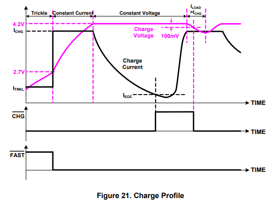
So let's now go over how charging works with this IC.
The MC34673 charges uses the standard charge profile with trickle, constant-current (CC), and constant-voltage (CV) modes. The CC and the CV charge modes are also called fast-charge mode.
When the input voltage rises above the internal power-on-reset threshold, which is 2.9V, the
It is worth noting that the battery system, as noted above, lets us know when the end of charge condition has been met. There is an EOC block that monitors the charge current and the battery voltage for the EOC conditions.
Also another that's worth nothing to point out is that there is a VIN-BAT comparator, VIN standing for input voltage feeding the IC and BAT standing for the voltage of the battery. The comparator monitors the difference between the input voltage and the battery voltage. The input voltage must be higher than the battery voltage for the charger to be enable. If the input voltage falls below the battery voltage, the charger is disabled to prevent leakage current from the battery to the input. So it is best to give an input voltage to the IC of at least about .1V higher than the battery voltage. Thus, if your battery charges at 4.2V, you should thrive to input at least 4.3V to VIN of the IC.
There is also die temperature feedback in the IC, which means the silicon of the chip is monitored for temperature. Temperature is an important part of charging because if the temperature reaches certain extremes, charging should be reduced or halted. Thus, temperature monitoring is important. Once the die temperature reaches the threshold temperature, which is 110°C, the charge-control blcock can reduce the charge current to prevent further die temperature rise.
The IC has a logic control block, which determines the on and off of the charger. It takes the signals from the VIN monitor, VIN-BAT comparator, EOC, and the external enable signal and determines the on and off states as well as the charge status indication outputs of the charger (
In summary, the MC34673 IC has a lot of features, in that it can act as a standalone battery charger (without a microcontroller) or as a battery charger connected to a microcontroller.
The high input voltage, up to 28V, ensures that no additional overvoltage protection is needed. Usually voltage does not exceed 28VDC into an electronic device.
No external MOSFET, reverse-blocking diodes, or current-sense resistors are required.
Trickle charge is provided for fully discharged batteries.
So let's now go over the pinout of this chip.
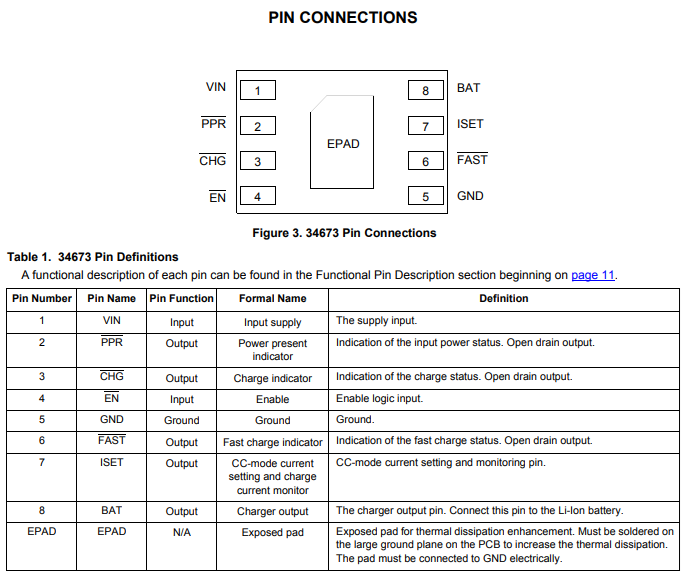
Every pin connection is probably self-explanatory except for the enable logic input.
We get a more in-depth explanation later in the datasheet that this IC is an active-low enable logic input. This means that it is active when it is at a LOW voltage. When left floating, connected to ground, or pulled to a LOW logic state, the charger is enabled. Pulling this pin to a HIGH voltage disables the charger.
So now let's see how the datasheet says to build the standalone battery charger with this IC, meaning the battery charger without any MCU connected to it (thus, standalone).
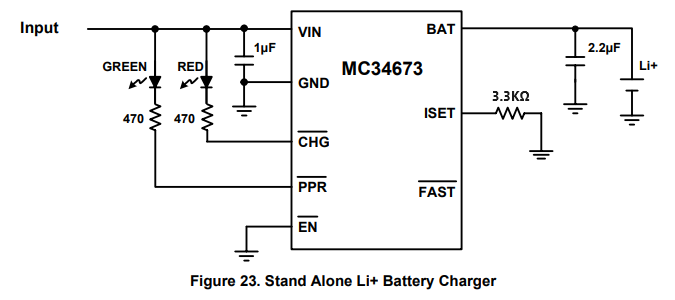
So to power this circuit, you can feed into 4.5-5V or higher.
The status LEDs is purely your choice. However, it is a good idea to have them to know what's going on in the circuit. The
The ISET pin is a very important pin, which we use to set the charging current. The resistor can handle up to 1.2A, so we push it near these limits. Using a 3.3KΩ resistor, we get close to that without exceeding the manufacturer's rating.
On the datasheet is a formula for the charging current, ISET.
This is shown below.
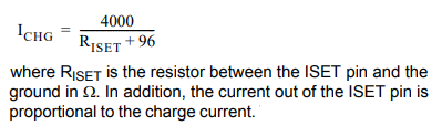
So if you plug 3.3KΩ into the formula, we approximately get near 1.2A.
If you want a different charging current, then you add input this charging current into the equation and then solve for RISET.
The next important pin is the battery pin. To this pin, we place the battery that charges. And in parallel to this, we can add our load, the device we're powering.
And this is all that is required to build a simple lithium ion battery charger.
Obviously, this battery isn't very advanced, only offering LEDS as status keepers of the circuit. This does not offer us a digital display of what charge the battery has and does not offer us a live update of the percentage as the battery charges, as does iphone, for example. For that, we would need another chip entirely, a battery fuel gauge, which can measure the current charge of the battery cell. This adds obvious complexity to the circuit. A battery fuel gauge uses an analog-to-digital converter for coulomb counting of a rechargeable battery. According to the datasheet for the BQ27Z746 datasheet, "The first ADC is an integrating analog-to-digital converter designed specifically for tracking charge and discharge activity, or coulomb counting, of a rechargeable battery. It features a single-channel differential input that converts the voltage difference across a sense resistor between the SRP and SRN terminals with a resolution of 3.74 µV. The differential input common mode voltage range is from VSS to VBAT and supports a 1-series cell high-side or low-side sensing option with ±0.1-V input range. The CC digital filter generates a 16-bit conversion value from the delta-sigma CC front-end. New conversions are available every 1 s."
With this setup, you would need a MCU, which reads the value output from the ADC. You would then have to convert this value using a formula to a percentage of the battery charge from 1% to 100%. You would have to add an LCD to the MCU, so that it displays this value in real time to the user. So this is a much more complex circuit than what you can build using the MC34673 chip alone.
Just to show you how the MC43673 would look interfaced to an MCU, the circuit is shown below.
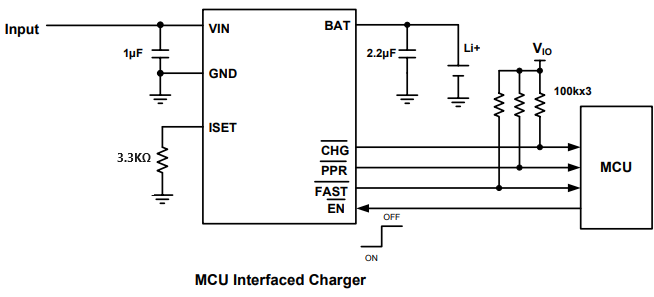
The only thing that really changes is that instead of connecting LEDs to the status pins, you connect them to the MCU. Also the enable pin you connect to the MCU; this way, you can choose to disable enable by sending it a HIGH voltage or enable it by keeping it a LOW logic state.
And this is how we can build a 1-cell lithium ion battery charger standalone charger.
Related Resources