
How to Build a NAND Gate with Transistors
In this article, we go over how to build a NAND gate circuit with transistors.
Transistors are the building blocks of logic gates, such as AND gates, NAND gates, and gates are the building blocks of integrated circuits.
With transistors arranged in certain ways, we can build the various gates that are used in electronics.
In particular, NAND gates are especially importantly and widely used because just by using NAND gates, any other type of gate can be constructed from them. This is the case also with NOR gates, but NAND gates are in more widespread use.
So from this article, you will not only learn how to build logic gates from discrete transistor components, but you learn more about how transistors operate in order to create gates. This teaches you more about the basic building blocks of electronic circuits, the transistor.
Any type of transistor can be used in order to create logic gates, including BJTs or FETs. However, in this article, we will use NPN BJTs in order to do it.
The 2N3904 transistor is a very common NPN BJT transistor which can act as a switch or an amplifier.
The NPN BJT transistor, just like a FET, has 3 terminals: these 3 terminals are the base, collector, and emitter.
The base functions as the turn-on switch. A small amount of current flowing through the base can allow a much larger current to flow from the collector to the emitter. The BJT functions as an electrical switch, in which if we feed a small current to the base of a transistor, it turns on a larger current from the collector to the emitter.
The components we need to build this circuit are shown below.
Components Needed
- 2 2N3904 Transistors
- 2 10KΩ Resistor
- 470Ω Resistor
- LED
So with just a few components, we can construct a NAND gate circuit.
Know that a NAND gate circuit only turns off the load if all transistors in the circuit are turned on by an adequate base current. If any transistor is OFF or not conducting current from the collector to the emitter, then the load will be on because of the pull-up resistor to the 5V power source.
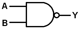
Below is the truth table for a NAND gate.
| NAND Gate Logic | ||
| Inputs | Output | |
| 0 | 0 | 1 |
| 0 | 1 | 1 |
| 1 | 0 | 1 |
| 1 | 1 | 0 |
So as you can see from the truth table, a NAND gate will have a HIGH output for all conditions except if both inputs are 1. In that case, the output will be logic LOW.
The circuit we will build is shown below.
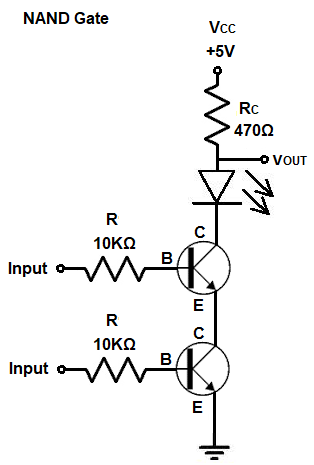
So what makes this a NAND gate?
You can see that the transistors are pretty much lined up series with each other. Current, therefore, only has one path to travel. If we connected the load to the emitter terminal of the second transistor, this would be a logic gate. Connecting the load to the collector terminal makes the circuit a NAND gate. Connecting the load to the collector terminal gives the NOT gate or inverter effect to the circuit.
The resistor RC functions as a pull-up resistor that pulls the LED up to the 5V voltage source so that the LED is powered on.
When both or any of the transistors are OFF, the LED is on.
If both transistors are ON, the pull-up resistor no longer has the same effect and the LED shuts off.
This setup with these 2 NPN BJT transistors with the output placed at the collector terminal functions as a logic NAND gate.
As stated before, transistors are the building blocks for ICs, because they form the logic gates which are used heavily in computers.
Arranging transistors in certain configurations allows us to build gates, which can then be used to form higher-level electronic devices such as registers, latches, etc.
Knowing how transistors can be used to create logic gates allows you to understand electronics at the lowest level, so that you can get the best understanding of it from the most basic fundamental level.
This, again, was done through NPN BJT transistors but it can also be done in a
similar fashion with FETs such as MOSFETs.
So this is how to build a NAND gate with transistors.
Related Resources