How to Build an RC Differentiator
In this project, you are going to learn how to build an RC differentiator circuit.
A differentiating circuit is a circuit that produces pulses or that fades out input waveforms from its peak value all the way down to zero. To show this visually, let's view the waveforms, which will show the result of this project.
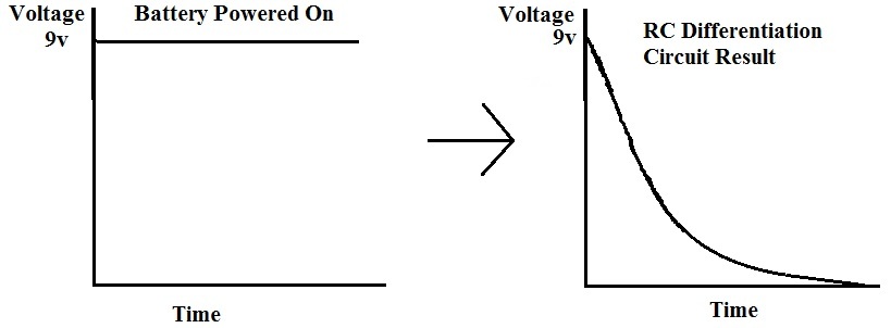
So you can see the input that we are putting into the circuit is a DC voltage of 9 volts, which is a straight line across against time. As the output, we get a waveform that first at the peak voltage of 9 volts of the battery but then fades out over time until it goes down to 0. So at the moment when the power switch is set to ON, the wave is at its highest level and then gradually fades out.
In this circuit we are going to be lighting an LED. So at the time we turn the switch ON, the LED will be at its brighest level, since it is receiving the peak voltage at the initial stage but then it will get dimmer and dimmer until it has completely faded out 1 or 2 seconds later.
Below is the schematic of this RC Differentiating Circuit:
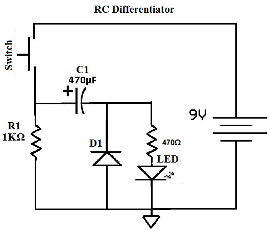
Now wire up the circuit. When you finish wiring, turn power ON. The LED lights up, then turns dimmer and immer, before it goes out 1 or 2 seconds later.
The basic components of the RC type differentiating circuit are R1 and C1. The value of R1xC1 is known as the time constant. With a larger value of R1 X C1, the wave takes a longer time to fade out, so the LED stays on longer. So R1 and C1 can alter the output waveform.
The 470Ω resistor is there to limit the current that goes to the LED, so it doesn't get blown out by excess current.
The diode, D1, serves as a protection diode, so in case, the voltage is switched around (accidentally), reverse current doesn't destroy the LED.