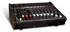
How to Build an Audio Mixer

In this project, we will build an audio mixer, which is a device that can add different audio signals together into one output. For example, say, one audio input is a cappella, with a person’s lone voice singing and another audio signal is background music. With an audio mixer, you can combine the background music with the singing to have an output as if both audio signals were together, in other words, mixed, which is the function of a mixer.
This project will serve to teach you about mixers and how they can be constructed cheaply using a few resistors, potentiometers, capacitors, and a JFET transistor. It will do everything that a mixer is supposed to do: combine signals from different signal sources, with the capability of being able to change the volumes of the input signal sources as well as overall volume of the mixer output.
To do this, only a few parts are needed, which are shown below:
- A 2N3819 JFET Transistor
- 3 10KΩ Potentiometers
- 3 100KΩ potentiometers
- 1 100Ω resistor
- 4 1 µF capacitors
- 10-volt power source
- 4 switches
Below is the schematic of the circuit we are going to build:

Operation of Circuit
A mixer is really nothing more than an adder. It adds all the different signals that are input into it and then combines the added signals into one. The input audio signal inputs are where the audio signals which are to mixed enter the circuit. This could anything from microphone input, to a music audio file, to a speech file, any type of audio input which can be connected to this mixer.
The 1µF capacitors which are directly after the audio signal inputs are coupling capacitors. These capacitors serve to only let the AC aspect of the audio signal through and block the DC aspect. Only the AC aspect of the signal represents the audio of the signal. The DC is unwanted and would cause offset to the signal. Therefore, this is why we use these coupling capacitors. After these capacitors are 10KΩ resistors which are then hooked up to 100KΩ potentiometers. These 100KΩ potentiometers serve as volume controls. They control the volume of each individual audio signal which is input into the circuit. Turning the potentiometer so that its resistance increases lowers the volume of that audio signal. Conversely, turning the potentiometer so that its resistance decreases increases the volume of that audio signal.
The 6.8KΩ resistor is just for biasing purposes, to make sure the output signal drops across the source of the JFET.
The 1µF capacitor on the output again serves as a coupling capacitor, so that only the AC signal goes to output and not any DC to cause offset.
The output signal contains all the audio signals tied into one channel, which is exactly how a mixer works.