
How to Calibrate the HSI Clock Signal in an STM32F407G Microcontroller Board in C

In this article, we show how to calibrate the HSI clock signal in an STM32F407G microcontroller discovery board, so that we can output the desired signal.
The HSI (High-speed Internal) clock signal is derived from an internal RC circuit within the STM32F407G discovery board.
One of the major factors that influence the accuracy of the HSI signal is the ambient temperature.
At 25°C, the HSI signal has an accuracy of ±1%, but the temperature range from below -40°C and above 105°C decreases the accuracy.
To compensate for this change from the baseline frequency, we can calibrate the signal to improve the accuracy. This may be important for communication peripherals.
In order to know whether the signal is accurate, you first have to measure the HSI signal. Once the HSI signal is measured, then This can be done through the RCC Clock Control Register (RCC_CR).
This register is shown below.
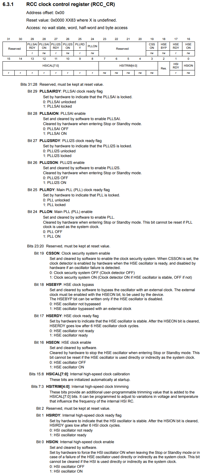
There are 5 bits labeled HSITRIM[4:0], which allows us to adjust the frequency of the HSI clock signal.
By default, the HSITRIM[4:0] bits are 10000, or 16 in decimal. This allows for the default 16MHz HSI clock signal.
However, if we decrease this trimming value to a lower value, this functions to decrease the HSI frequency.
If we increase this trimming value to a higher value, this functions to increase the HSI frequency.
Each incremental value serves to increase or decrease the frequency by about 0.5%, which is approximately around 80KHz.
This means that if instead of the default trimming value of 10000 (decimal 16), we increase the value by 1 to 10001 (decimal 17), the frequency will be increased by about 80KHz. If 10000 produces a calibration of 16MHz, then 10001 calibrates this signal to around 16,080,000Hz or 16.08MHz.
This means that a trimming value of 11111 produces an HSI frequency that is 1.2MHz greater than the default frequency of 16MHz.
A trimming value of 01111 produces an HSI frequency that is about 80KHz less than the default freuqency of 16MHz, which is 15,920,000Hz or 15.92KHz.
A trimming value of 00000 produces an HSI frequency that is about 1.2MHz less than the default frequency of 16MHz.
This way, we can calibrate the HSI signal to produce the desired accurate signal.
Once again, changing the trimming value incrementally by 1 allows us to modify the signal 0.5% (about 80KHz).
So first check the HSI signal and then calibrate as needed based on this reading.
Below we have a program that sets the trimming value of the HSITRIM bits
of the RCC_CR register to 10001.
So this is a very basic program.
We first get the base address of RCC, which is 0x40023800.
We then have the offset for the RCC_CR register, which is 0x00
We then can calculate the address of the RCC_CR register, by adding the base RCC address with the offset.
We then create a pointer variable, pointing to the address of the RCC_CR register.
We then dereference this variable and set the HSITRIM bits to 0x11,
which is
10001 in binary. This calibrates the frequency to about 80KHz higher than the default
frequency.
So this is how to calibrate the HSI clock signal
in an STM32F407G microcontroller board.
Related Resources