
How to Configure a General-purpose Timer for PWM Output STM32F446 Microcontroller Board in C
In this article, we show how to configure a general-purpose timer for PWM output in an STM32F446 microcontroller board in C.
General-purpose timers are so called because they can be used for a variety of purposes, including measuring the pulse lengths of input signals (input capture) or generating output waveforms (output compare) such as square waveforms or PWM output.
The TIMx capture/compare mode register 1 allows us to select the type of output compare waveform we desire. We can select an output waveform such as toggle (which produces a perfectly square waveform) or we can select output such as PWM, where we choose the waveform's duty cycle.
PWM, or pulse width modulation, is used for various circuits including stepper motor circuits or DC motor circuits, along with several other applications. Therefore, knowing how to configure a general-purpose timer to output PWM signals is important.
So in this program, we will use timer 2 as the timer we will use to produce PWM output.
Timer 2 is a 32-bit general-purpose timer.
In this program, we will configure timer 2 to produce PWM output in which the entire cycle lasts for 3 seconds, with the duty cycle being 33%, meaning the PWM output is on for 33% of the time, or 1 second and off for 66% of the time, or 2 seconds. Later, once you master how to set up the duty cycle and periods for PWM output, you can customize these values.
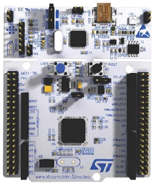
We create an output channel for this timer 2 on channel 1 on pin PA5. When pin PA5 is in AF1 alternate functionality, it acts as TIM2_CH1. Therefore, the output PWM signal goes to this channel. Pin PA5 has an onboard green LED connected to it, so we will see the effects of the PWM signal on this LED. What you will see is the LED turns on for 1 second and off for 2 seconds and repeats over and over again.
Thus, you won't need any special equipment like an oscilloscope to be able to see the effects of the PWM output.
We need 2 major code files in order for this code to work.
We need our header file, which contains many macros and structures that describe the various registers and needed values.
We then need our main C file, which contains the code that creates our PWM output from timer 2.
Below is the header file, which we name
stm32f407xx.h
The contents of the main.c file is shown below.
The first thing we must do is include the stdint.h header file and our stm32f446xx.h header file in our main.c file.
We create a function protoytpe for our tim2_init() function, so that the compiler knows its return type, what arguments it accepts, along with its data type.
We then have our main() function.
Within this main() function is our tim2_PWM_init() function.
We then go to this tim2_PWM_init() function.
So, in this function, we first enable the peripheral clock for GPIOA. This is because we are using pin PA5 to act as an output channel for timer 2, specifically to act as TIM2_CH1.
In order for pin PA5 to act as a channel output, we must configure the pin to alternate function mode.
To get the pin to act as TIM2_CH1, we configure the AFRL to AF1 mode.
So now all is set for pin PA5.
Next, we enable clock access to timer 2.
We set the prescaler register to 16000 -1.
What this does is it decreases the clock frequency to 1KHz.
The timer uses the system clock as its clock source. The system clock is the internal RC clock, which is 16MHz.
The timer prescaler register divides this clock source by the number placed into it. 16,000,000/16,000= 1KHz.
By we need to further decrease this signal.
So we feed, 3000-1, into the auto reload value.
This further decreases the clock signal from 1KHz to 0.33Hz.
T= 1/0.33Hz= 3 seconds. So the time period of this signal is 3 seconds.
We then clear the counter register, as is custom of doing.
We then must set timer 2 in PWM mode. This is done through the TIMx capture/compare mode register 1.
This register is shown below.
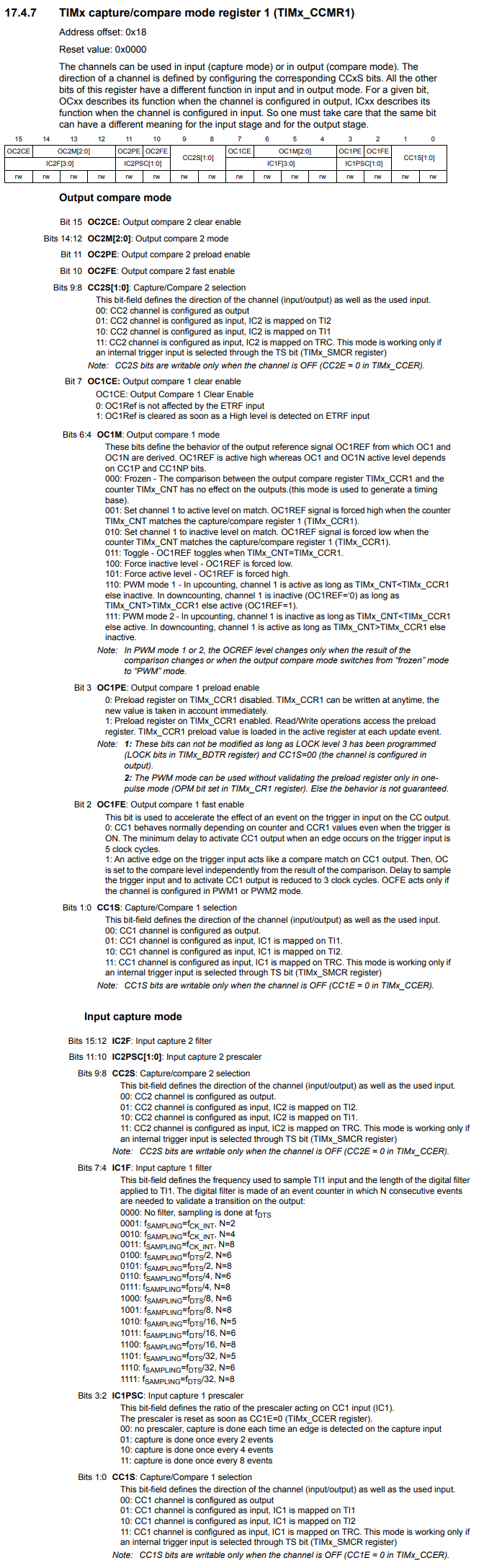
You can see that bits 6:4, OC1M bits (Output compare 1 mode) is how we set the timer to PWM mode. So we set the timer to PWM mode 1 by setting these bits to 110. This is what we do with the line, pTIM2->CCMR1 |= (0b110 << 4);
We then have to enable the capture/compare. We do this through the TIMx capture/compare enable register (TIMx_CCER). We do this by setting bit 0, CC1E (Capture/Compare 1 output enable), to HIGH.
Next, we set the duty cycle of our PWM signal.
Previously, we set the period of PWM signal to 3 seconds.
Now we need to set the duty cycle of our PWM signal, and this is done through the TIMx capture/compare register 1 (TIMx_CCR1).
We feed a value into this register to determine the duty cycle.
An easy way of selecting this value is to base it off of the value that you entered into the auto reload value register, which is shown in the line, pTIM2->ARR = 3000-1;
So 3000 represents 100% of the PWM signal.
Now if you want a third of that, then you would feed a 1000 into the CCR1 register, which is what we did in the line, pTIM2->CCR1 = 1000-1;
If you want a 40% duty cycle, you would fee in 1200 (3000 * 40%= 1200) into the CCR1 register.
If you want a 20% duty cycle, you would feed in 600 (3000 * 20%= 600) into the CCR1 register.
If you want a 10% duty cycle, you would feed in 300 (3000 * 20%= 300) into the CCR1 register.
Lastly, we enable timer 2.
And this is all that is necessary to configure a general-purpose register for PWM output with an
STM32F446 microcontroller board in C.
Related Resources