
How to Configure the Prescaler for a Bus in an STM32F407G Microcontroller Board in C

In this article, we show how to configure the prescaler for a bus in an STM32F407G microcontroller discovery board, so that we can decrease the clock signal for a particular bus.
So the clock system of an STM32F407G discovery board has a number of prescalers so that we can modify the clock signal for specific buses within the system.
These prescalers can be set in code in a language such as C, which is what we'll use in this case.
This is all done by modifying the RCC clock configuration register (RCC_CFGR). It is this register where we set the value of the prescalers for any of the peripheral buses within the bus architecture system.
To see this better, let's look at 2 diagrams.
The first diagram we'll look at is the STM32F407G block diagram.
This shows us the bus system architecture of the microcontroller.
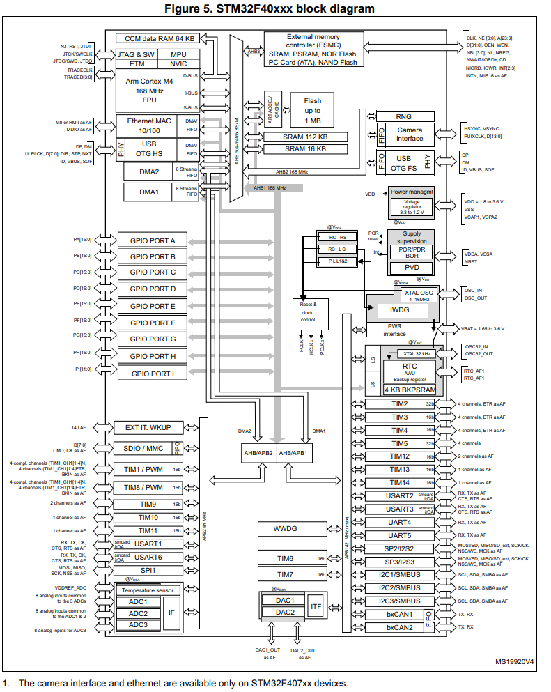
Looking at the diagram, you can see there's a main AHB bus, which then branches off into an APB1 bus and an APB2 bus.
An important thing to note is the maximum frequency that each bus can handle.
the maximum frequency for the AHB bus is 168MHz.
The maximum frequency for the APB1 bus is 42MHz.
The maximum frequency for the APB2 bus is 84MHz.
You must know these because you don't want to feed a clock signal greater than these frequencies into the bus, as it won't be able to keep up with the high frequency above these ranges.
So now let's look at another diagram, an even clearer diagram when talking about clock systems, which is the clock tree of a microcontroller.
Below is the clock tree, which is the clock system or
hierarchy, for the STM32F407G micrcontroller board.
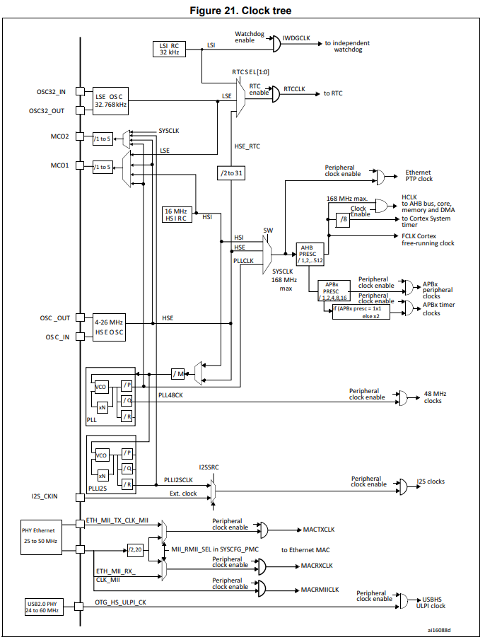
This is even a better diagram, because it's specifically dealing with clocks.
In this diagram, you can see each of the prescalers for each of the bus systems.
So a clock can originate from a couple of different sources, such as the HSI, HSE, or PLL clock sources.
At this point, the originating clock is the system clock.
This clock signal then goes to bus prescalers, the first being the AHB prescaler.
By default, each prescaler is set to /1, which keeps the clock signal at the frequency.
However, you can decrease this frequency by setting the prescaler to another value. You can decrease it by /2, /4, /8, or /16.
After the AHB prescaler, there are APB1 and APB2 prescalers, which can further prescale down to lower clock signals, depending on your needs.
If you look again at the block diagram, you can see which components are connected to which bus. So you can determine what frequency you need for a given component.
So now let's look at the register which we need to set in order to configure the prescaler for a specific bus for the STM32F407G microcontroller.
Below is the RCC clock configuration register (RCC_CFGR).
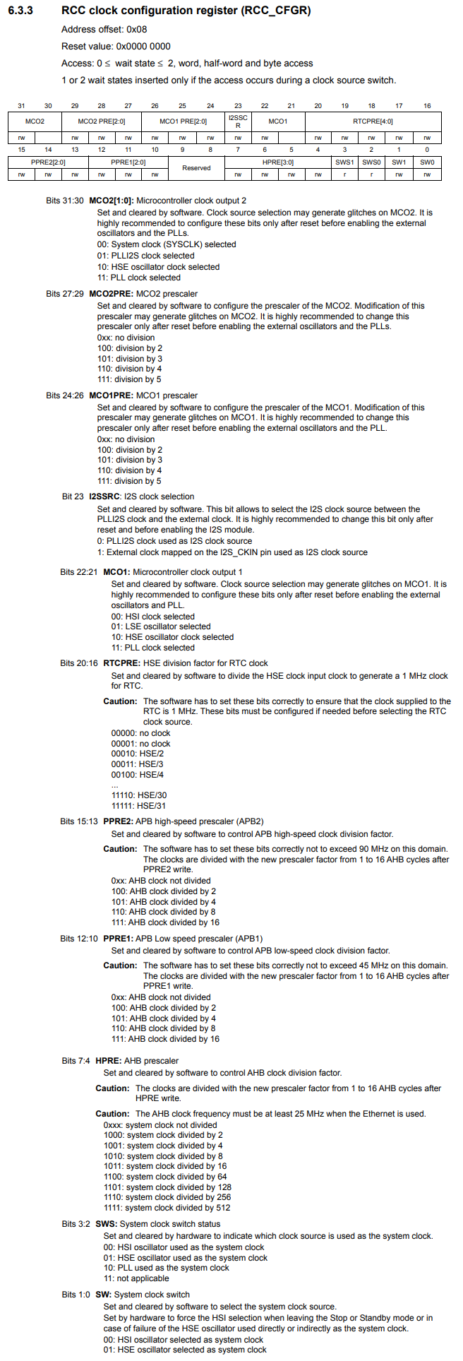
So the RCC clock configuration register is how we configure the prescaler for a specific bus in the STM32F407G microcontroller board.
Bits 7:4 HPRE is how we configure the AHB prescaler.
Bits 12:10 PPRE1 is how we configure the APB1 prescaler.
Bits 15:13 PPRE2 is how we configure the APB2 prescaler.
So if we want to set the APB2 prescaler to /2, then we set the bits 15:13 to 100. If we want to set the APB2 prescaler to /4, then we set bits 15:13 to 101. If /8, then 110. If /16, then 111.
The APB1 prescaler would be the same bits for bits 12:10.
The AHB prescaler is set using 4 bits, bits 7:4. The AHB prescaler divides the system clock, as the clock signal before the AHB prescaler is the system clock. To divide the system clock /2, then we set the bits to 1000. For /4, then 1001. For /8, then 1010. For /16, then 1011. For /64, then 1100. For /128, then 1101. For /256, then 1110. For /512, then 1111.
So now that you know that this is the register we must configure to set the prescaler for a specific bus, let's now go through the C code that accomplishes this.
This code below modifies the APB2 prescaler to divide the clock signal by 2.
In order to do this, we write 100 to bits 15 to 13.
Being that the reset
So let's now go over this basic code.
So since we're dealing with clocks, the base register is the the beginning of RCC, which is 0x40023800UL
Next, we need to be able to reference the RCC_CFGR register. This has an address offset of 0x08
So after that, we're able to get the full address by addressing the RCC base address with the address offset.
We then create a pointer variable, which points to this address.
We then dereference this and set bit 15 to 1.
Remember, Bits 15:13 PPRE2 is how we configure the APB2 prescaler.
100 sets the prescaler to /2.
Since the reset value is 0x0000 0000, all we need to do is set bit 15 to 1.
This sets the APB2 prescaler to /2.
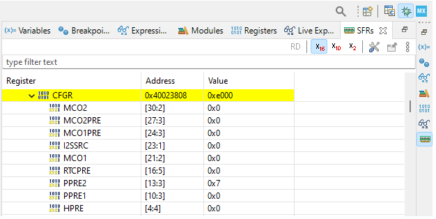
We check the bits in the PPRE2 bits of the RCC_CFGR register and verify that is 0x4 in value or 100 in binary.
This is shown in the SFRs view below.

Let's do another example, this time setting the same APB2 prescaler to /16.
To set the prescaler to /16, we feed 111 into bits 15:13.
You can either feed in 0b111 into bit 13 or you can convert this number into hexadecimal (0x7) and feed it into bit 13, or you can set 1 individual to each bit (bit 13, 14, and 15).
Below is our code to set the APB2 prescaler to /16.
Now the prescaler is set to /16.
We check the bits in the PPRE2 bits of the RCC_CFGR register and verify that is 0x7 in value or 111 in binary.
This is shown in the SFRs view below.
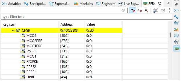
As one more example, let's set the AHB prescaler to /128.
Remember that this is the HPRE bits within the RCC_CFGR register, which are bits 7:4
To set the prescaler to /128, we feed 1101 into these bits.
In hexadecimal, this number is 0xd
So we feed 0xd into bits 4-7.
This is shown in the code below.
So this code divides the system clock by 128.
We check the bits in the HPRE bits of the RCC_CFGR register and verify that is 0xd in value or 1101 in binary.
This is shown in the SFRs view below.
So this is how to configure the prescaler for a particular bus
in an STM32F407G microcontroller board.
Related Resources