
How to Configure the Prescaler for an MCO pin in an STM32F407G Microcontroller Board in C

In this article, we show how to configure the prescaler for an MCO pin in an STM32F407G microcontroller discovery board, so that we can decrease the clock signal outputted from an MCO pin, either the MCO1 pin or the MCO2 pin.
Why would we want to prescale down the clock signal from an MCO (MCO stands for Microcontroller Output) pin?
This is a special pin because with a signal-measuring device such as an oscilloscope or a logic analyzer, we can measure the system clock of the microcontroller board.
The reason we would want to prescale the clock signal ouputted from an MCO pin is if our signal-measuring device, whether it be an oscilloscope, logic analyzer, etc., has frequency constraints .
For example, say you are using a 16MHz clock signal, but your logic analyzer can only measure up to 8MHz. In this case, you would want to prescale the clock signal by about 4, so that you can measure the signal with the instrument you have.
This way, you can measure a signal with hardware that has frequency constraints.
By using the clock prescaler for the MCO pin, this doesn't decrease the clock signal. The clock signal remains the same. This only decreases the clock signal at the MCO pin just for testing purposes, to see what signal is being outputted.
Therefore, the original system clock signal is undisturbed.
So in order to set the prescaler of an MCO pin, we must configure the bits of the RCC Clock Configuration Register.
This is shown below.
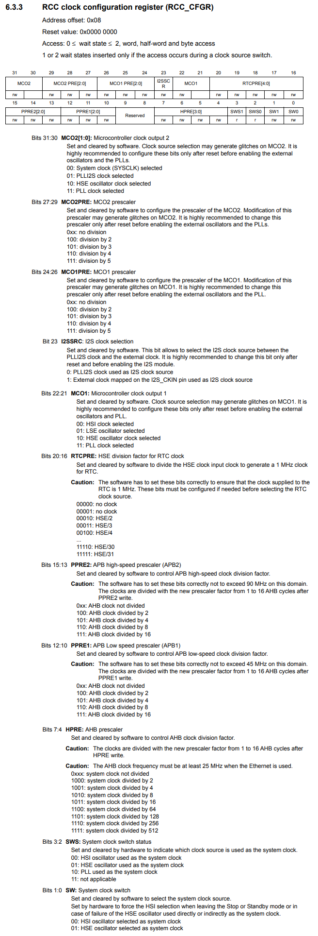
So in order to configure the prescaler for the MCO1 pin to /4, we need to set the MCO1PRE bits (bits 26:24) to 110.
The datasheet for the STM32F407G discovery board is actually wrong. The MCO1PRE bits are bits 26:24, not 24:26.
So now you know that we have to set the MCO1PRE bits to 110 in order to
configure the MCO prescaler to /4.
So we first need the base address of the RCC clock. This is the address, 0x40023800
We then need the address offset for the RCC_CFGR register, which is, 0x08
The address for the RCC_CFGR register is then the base address plus the address offset.
We then create a pointer variable pointing to this address of te RCC_CFGR register.
We then set this variable to 110 (hex 0x6) for bits 26:24.
So this is just to set the MCO1 prescaler to divide the incoming clock signal by 4.
In this article, we will output a 16MHz HSI signal and use the MCO1 prescaler to decrease it 4 times to 4MHz.
Below we show the full code to output a 4MHz clock signal from MCO1 pin. The original signal is a 16MHz HSI signal, which we then divide by 4 through the MCO1 prescaler.
The MCO1 pin is Pin A8 of the microcontroller board.
In order to configure PA8 as an MCO1 pin, we must set it in alternate function mode to function as MCO1.
Before, we can use the GPIO Port pin PA8, we must enable the peripheral clock for this port.
This is all shown below.
So this is the full code to output a 4MHz HSI signal from the PA8 pin which acts as the MCO1 pin of the microcontroller, where the system clock is a 16MHz HSI signal.
We can now measure the signal with a device that may have frequency constraints, which otherwise would not be able to measure the signal due to it being too high in frequency.
This is why using a prescaler for an MCO pin can be very important.
You can do the same with the MCO2 pin by adjusting the MCO2PRE bits of the
RCC_CFGR register, which are bits 29:27.
You then would have to configure pin PC9 to function in alternate function mode as MCO2.
So this is how to configure the prescaler for an MCO pin
in an STM32F407G microcontroller board.
Related Resources