
How to Connect a LM386 Audio Amplifier Chip to a Circuit
A LM386 is a very popular audio amplifier chip that allows a user to amplify sound. It's widely used, very popular.
Thus, in this tutorial, we will go over all the aspects of this chip including the pinouts of its terminals and how to connect it to a circuit.
Diagram
Pin Terminals
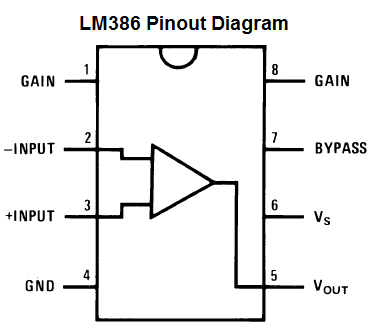
Terminals 1 and 8 represent the gain control of the amplifier. These are the terminals
where you can adjust the gain by placing a resistor and capacitor or just capacitor between these
terminals. In this circuit, we will place a 10µF capacitor between these terminals for the highest voltage gain.
Terminals 2 and 3 are the sound input signal terminals. These are the terminals where you place
the sound which you want to amplify. Terminal 2 is the -input and Terminal 3 is the +input. In our circuit,
the positive sound signal will be placed on terminal 3 and terminal 2 will be tied to ground.
Terminal 4 is GND (ground) and will be tied to ground in the circuit.
Terminal 5 is the output of the amplifier. This is the terminal in which the amplified sound signal comes out.
Terminal 6 is the terminal which receives the positive DC voltage so that the op amp can receive
the power it needs to amplify signals.
Terminal 7 is the Bypass terminal. This can bypass 15KΩ resistors. This pin is usually
left open or is wired to ground. However, for better stability, a capacitor is added in our circuit because this can prevent
oscillations in the op amp chip.
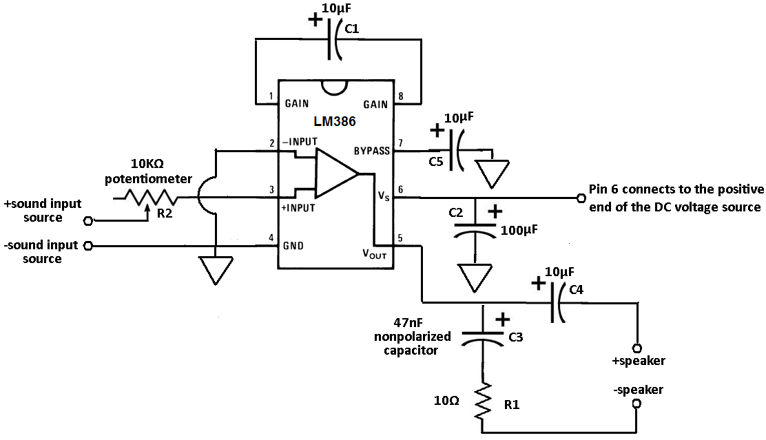
Below is the LM386 circuit we will be hooking up:
Explanation of Additional External Components
C1 is a capacitor that is used to set the gain of the op amp. By placing a
capacitor here, we can set
the gain to the highest level to get maximum gain, which in this case is 200. Therefore, the voltage
coming out of the op amp is 200 times the voltage going in.
C2 is a smoothing capacitor. If the power supply has any abrupt voltage or current spikes, this capacitor
works to smooth out the signal so that it evens out those spikes. This capacitor helps to eliminate
all of those ripples, which translates to the op amp having less noise input into it.
C3 acts as a current bank for the output. This capacitor fills with electrons when demand for current
is low and drains when sudden surges of current occur.
C4 is a coupling capacitor. It removes any DC offset from the output of the LM386 amplifier and only
passes the (AC) sound signal through.
C5 improves the stability of the LM386 amplifier to prevent problems such as oscillation. OScillation
can turns familiar sounds into the unrecognizable.
In a Nutshell
The LM386 amplifies the sound input into it by a factor of 200. All amplifiers need DC voltage in order to run. The LM386 takes anywhere from 4-12 volts of DC voltage to operate. The sound signal to be amplified are placed on terminals 2 and 3. The amplified sound signal then exits through terminal 5. After a few capacitors and a resistor to filter out unwanted noise that may be on this signal, we connect the speakers to play out the amplified sound.