How to Connect a Full Wave Rectifier
In this article, we will now show how to connect a full wave rectifier to a circuit in order to get DC output.
A full wave rectifier has valuable use when a user takes an AC signal and wants DC output in exchange. A full wave rectifier converts the AC signal into DC, in the event that a device needs to be plugged into an AC outlet but needs to be powered and run on DC voltage.
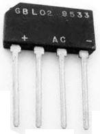
Pinout
A full wave rectifier normally has 4 pins.
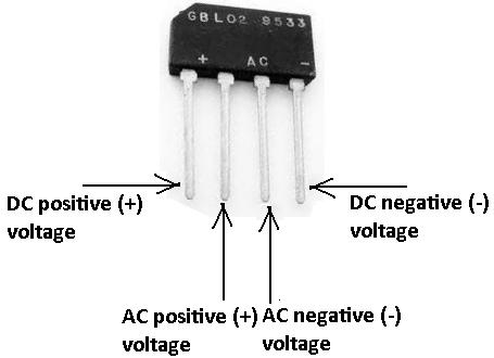
Pinout Terminals
The terminal that has the + symbol is the DC positive voltage. This is terminal that
receives the converted positive DC voltage that is output by the rectifier.
The terminals that have the two AC signals ( ) are the two terminals where you place the incoming AC voltage, which
you want to convert into DC. It doesn't matter the polarity. The positive and negative AC voltage can be
switched.
) are the two terminals where you place the incoming AC voltage, which
you want to convert into DC. It doesn't matter the polarity. The positive and negative AC voltage can be
switched.
The terminal that has the - symbol is the DC negative or ground voltage. This is the terminal that
receives the converted negative DC voltage that is output by the rectifier.
This is a diagram to visualize how a full wave rectifier works:
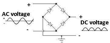
A full wave rectifier takes an AC signal input into it, such as the AC signal from a power outlet, and converts it into a DC signal. The AC is input. The DC is output.
To create a more smooth and steady DC signal, a smoothing capacitor is normally added in parallel to the output of the rectifier.
And to make it even more smooth and steady, a voltage regulator
can then be added in parallel to that to output to produce a specific DC voltage that you want as output.
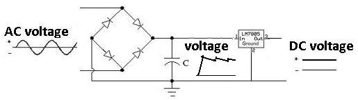
You can see after the smoothing capacitor that the voltage is pretty steady but not quite.
After the voltage regulator, it should be perfectly steady and even.
This will produce the most precise DC voltage. To learn how to connect a voltage regulator, see
How to Connect a Voltage Regulator to a Circuit.