
How to Connect a Pull Up Resistor
In this project, we will show how to wire up a pull up resistor to a circuit.
A pull up resistor is a resistor that makes the pin of a chip normally HIGH and then turns it LOW when switched on.
Pull up or pull down resistors are normally connected to the pins of chips so that they can define the state of the pins.
Pins of chips can be in any of 3 states.
They can be LOW, meaning a voltage near 0V (or below half of the voltage fed into the power supply of the chip) is fed into the pin.
Pins can be HIGH, meaning a voltage above half of the voltage fed into the chip's power supply is fed into the pin.
Or pins can be floating, meaning they are unconnected to either a LOW or HIGH voltage. In this case, the pin may go randomly between LOW or HIGH. Pins may float because they have no clear defined voltage signal going into it. Things such as external noise may allow it to haphazardly take on both values.
It is undesired for pins to float. And this is why we normally want the signal going into a pin to be clearly defined. That way, we know for sure whether it is LOW or HIGH. And this is why we use pull up and pull down resistors.
Pull up resistors pull up a pin to a HIGH state.
Pull down resistors pull down a pin to a LOW state.
When connected to a switch such a pushbutton, the states of the pins can then be switched to the other when switched on.
We will show now how to connect a pull up resistor to a pin of a chip so that a pin can be normally HIGH and then switched LOW when a switch such as a pushbutton is pushed down.
One of the best circuits to test pull down resistors on are logic chip circuits. Logic chips are chips that work purely based on LOW or HIGH signals.
A NAND gate is a logic chip that outputs a HIGH signal only when one or both inputs of the gate are LOW. It will output a LOW signal if both of the inputs are HIGH.
We will connect both inputs going into a NAND gate to pull up resistors. This will make the pins normally HIGH. So normally the inputs will be at a logic HIGH level. So the output will be LOW and the load will not be powered on. When a pushbutton is pressed, then the pin will be drawn to a HIGH state. When both pushbuttons are pushed down and are, thus, HIGH, then input will have a LOW state, and the output will be HIGH and power on the load on its output pin.
This circuit will perfectly demonstrate pull up resistors.
Components Needed
- 4011 NAND Gate Chip
- 2 10KΩ Resistors
- 2 Pushbuttons
- LED
- 330Ω Resistor
The 4011 quad NAND gate chip can be obtained very cheaply from a number of online retailers for just a few cents. One place it can be obtained from is Tayda Electronics at the following link: Tayda Electronics- 4011 Quad 2-Input NAND Gate IC. However, it is a very popular chip and many electronics parts suppliers have them.
The pinout of the 4011 is shown below, so that you can see how to connect it in the circuit.
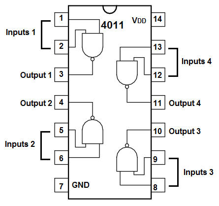
Each NAND gate has 2 input pins and 1 output pin.
We will use 2 pushbuttons as our inputs to the NAND gate.
The values we will use for the pull up resistors are 10KΩ.
The other components we need are the LED and the 330Ω resistor in series to limit current to the LED so that it
doesn't burn out.
Pull Up Resistor Circuit Theory
The perfect model of a pull-up resistor circuit is shown below.
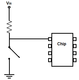
This pull up resistor circuit can be used exactly as is for every pull up resistor circuit.
The pin of this chip will be HIGH normally and when the switch is closed drops to LOW.
How this circuit works is the resistor is directly connected to the positive voltage. Due to the open switch, no current flows through the circuit; therefore, no voltage builds up across the resistor. All of the voltage is contained across the power supply. So the voltage at (either) end of the resistor is equal to the power supply voltage.
When the switch is closed, now the pin makes direct contact with ground and is now at a LOW state. Current flows through the circuit, so voltage is able to build up across the
resistor. Being that practically all of the power supply voltage falls across the resistor, the voltage after the resistor is essentially 0V.
NAND Gate Circuit Using Pull Up Resistors
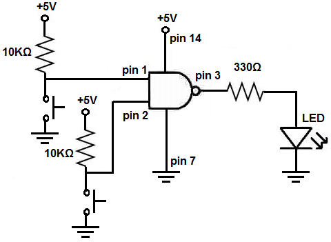
The schematic diagram of the NAND gate circuit using 2 pull up resistors at the inputs to the gate is shown below.
Below is the breadboard schematic version of the above circuit so that you can see the exact wiring of the circuit to the 4011 chip.
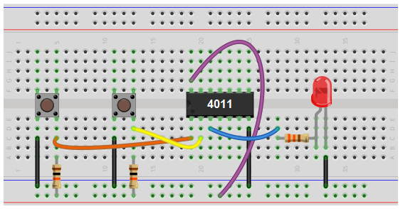
First and foremost, we must give power to the chip. We will feed it 5V of power, so we give +5V to pin 14 and we connect pin 7 to GND. This establishes power to the chip.
Next we connect pull up resistors to each of the inputs of the NAND gate. A pull up resistor circuit first has a resistor connected to positive voltage and then a pushbutton connected to ground. When the pushbutton is not pushed, each of the pins of the NAND gate will be HIGH. When a pushbutton is pressed down, the pin of the chip now makes direct contact with ground and falls to a LOW logic level. For a NAND gate logic, if one or both of the inputs are LOW, the output will be HIGH. So when both pushbuttons are unpressed, the output will be LOW and the LED in the circuit will be off. When either or both of the pushbuttons are pressed down, the output will be HIGH and the LED will turn on.
And this illustrates the use of pull up resistors. When working with chips, they allow a chip to have a pin that is normally HIGH, and then which can be
switched LOW.
Related Resources
How to Connect a Pull Down Resistor