
How to Connect a In-Circuit Serial Programming (ICSP) Interface
Many microcontrollers come with In-Circuit Serial Programming (ICSP) connectors.
These connectors allow for in-circuit serial programming. This is programming in which data is moved to a microcontroller serially and the microcontroller then executes these instructions.
Many microcontroller starter kits contain ICSP connectors.
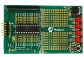
One such starter kit is the Pickit 2 starter kit; its ICSP connector is shown below:
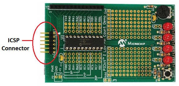
The ICSP connector is the 5-pin connector at the end of the development board. The PIC programmer plugs directly into the ICSP connector, so that the microcontroller can be programmed.
The PIC programmer has a USB connector so that it can plug into the USB port of a computer. When software is executed, the data runs from the computer, through the USB, into the PIC programmer, through the ICSP connector, and then to the microcontroller, that executes the code.
However, in order for this to occur, the ICSP connector must be interfaced to the PIC programmer properly, or else signals may be transmitted unclearly.
We will now discuss how to properly interface ICSP connectors, so that clear signals will be
communicated between the two. The biggest hang-up of ICSP connectors is that the serial communication programming
signals can get affected by the circuitry connected to the PIC. For this not to happen, we must set up the connector
properly to interface with the PIC programmer.
ICSP Pinout
Before we talk about how to interface the ICSP, you have to know each out the ICSP's pins, its pinout.
Below is a diagram of the pinout of the ICSP connector.
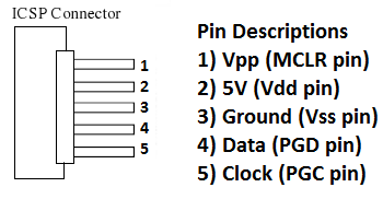
So, once again, with the ICSP, we have 5 connections: 5V (Vdd pin), Ground (Vss pin), Vpp (MCLR pin), Data (PGD pin) and Clock (PGC pin).
If the clock or data pins are not able to send the correct signal, the PIC will not program
properly and you will get an error.
ICSP Connector Schematic
Now we will go over the actual schematic of how the ICSP connector should be interfaced with the PIC programmer.
Below is a schematic of the Pickit 2 ICSP interface.
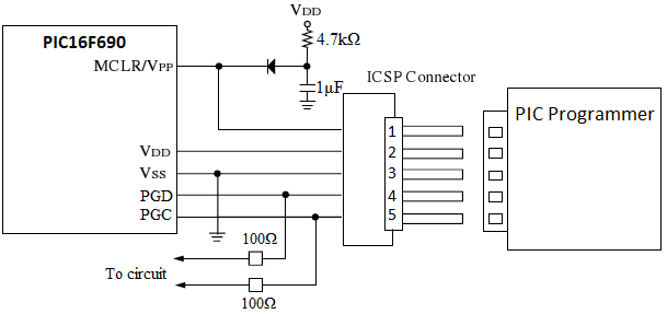
So the above schematic shows the ICSP connections. This is the correct schematic.
The schematic below will now show common errors when hooking up the ICSP connect to the programmer.

This schematic shows all the possible connection issues to watch out for in connecting the ICSP. Because of the way the ICSP feature works, you don't want to add any capacitance to the programming connections, since this can delay the signals. Even the capacitance on the Vdd line should be precise, as per the PIC programming specification. The PIC programmer actually cycles the Vdd line off and on while sending the Vpp signal to the MCLR pin. This is done to put the PIC into programming mode. If there is too much capacitance, it may slow the signal down and not meet the programming specs.
You also don't want to load down the clock or data signals. This is why capacitors should not be added to these lines. Capacitors may slow, or load down, the signal and cause interference and signal degradation. This why the capacitors are crossed out. The diodes connected to the Data and Clock lines are also a mistake becasue the Data and Clock lines need two-way communication when programming and verifying the part. A diode only allows one-way communication, so it cannot be added. It's pretty obvious why they should not be on the line.
Less obvious is the diode between the MCLR reset circuit and the MCLR/Vpp pin. This is recommended because the PIC programmer sends a high voltage signal to the Vpp line of around 12V-13.5V for a short period of time. You don't want that signal feeding into your Vdd regulator. This is actually just a safety precaution, though, because the current entering the MCLR pin is extremely small and the MCLR pull-up resistor will knock it down to prevent any damage.
Another recommendation which is often not used are the series resistors on the PGC and PGC lines between the PIC and the rest of the circuit. These resistors help isolate your circuit from the PGD and PGC signals so that your circuit doesn't load down the PIC programmer. This is the most common area where a problem may occur with ICSP. 100Ω resistors should not affect your circuit function but it should be plenty of resistance to isolate the programmer.
You will notice that when you get your Pickit 2 starter kit board, it doesn't have any of the interfering
components (capacitors, etc.) that would cause signal issues but it also doesn't have the 100Ω resistors. When
using the starter kit for future projects, keep this in mind. Without the 100Ω resistors added, it is possible
that your circuitry tied to the PGC or PGD pin can prevent the PIC programmer signals from getting through. By temporarily disconnecting
those pins, the problem can be solved, but it also can be solved by having these resistors in place.