How to Connect an LED Bar Graph to a Circuit

In this article, we show how to connect an LED bar graph to a circuit.
Before we go how to connect it, let's first go over how the LED Bar graph is internally connected inside, so that
you can know how to hook it up when we do.
Internal Construction of LED Bar graph
An LED Bar graph is just 10 individual LEDs inside of a single package. Each LED is separate, with its own anode and cathode terminal.
If you were to see the inside, the internal construction, of an LED bar graph, it would look like this:
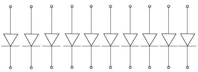
As you see, it's just 10 LEDs. One side of the bar graph is composed of the anode terminals. The other side is composed of the cathode terminals.
The anode terminals are the side of the LED which receives the positive DC voltage, so that the LEDs can be powered
on.
Which Side is the Anode Terminals and Which Side is the Cathode Terminals?
The next thing you must know before you can connect the LED bar graph is you must know which side is anode terminal and which side is the cathode. Otherwise, you will not be able to connect it. LEDs are diodes, so they must be connected with the correct orientation of polarity. LEDs will not light up if connected the wrong way in a circuit.
So how do we determine which side is which?
And this is simple enough. Usually, the LED bar graph is marked by the manufacturer. Pin 1 on the anode side is usually marked with either a dot or some type of indentation, that makes it obvious that this is anode of pin 1.
Look below at the obvious indentation marking the anode side:
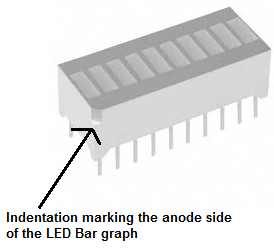
You can see the obvious indentation or groove in the above LED marking its anode side. Different manufacturers follow different protocols. Some may use a dot, some may create an
angular curve on the side of the LED containing the anodes. If you're confused about how to know which side is the anode and which is the cathode, consult the datasheet of the LED bar graph and
likely the answer will be there.
Connecting the LED Bar graph
Now that you know the anode side from the cathode side, you can connect the LED.
As always when working with LEDs, connect 220Ω to each of the 10 LEDs. This limits current to the LEDs, so that they won't be exposed to too much current and be damaged.
So now the schematic of the LED bar graph circuit will look like:
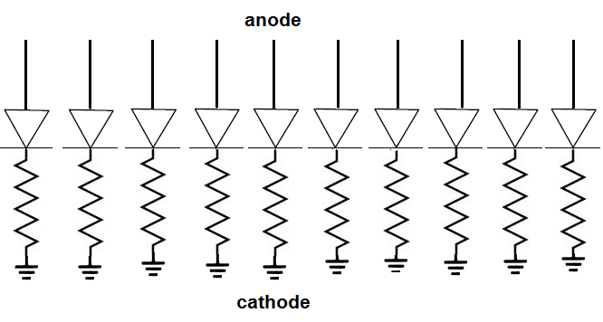
Here in this circuit, we have the anode side unconnected. It will be connected to voltage eventually so that we can power it, so that the LEDs of the bar graph can light up. But for now, they are unconnected. The cathode terminals are connected to ground.
In order to really utiilize an LED bar graph, you're going to have to use a microcontroller to vary the output of the bar graph. You cannot simply just connect voltages to the bar graph. LEDs in the bar graph may light up spaces apart, which is undesired. A bar graph must be in sync. It can only light up sequentially. Therefore, we need a system in place so that the lighting up happens orderly. And we do this by connecting each of the anode terminals of the LEDs to the output pins of a microcontroller. A very common microcontroller that is used is the Arduino. Once the anode terminals are connected to the output terminals of the arduino microcontroller, the arduino can be programmed to light up each LED in the bar graph sequentially, since they are connected to its output pins.
Below is an illustration of this circuit connected to an arduino:
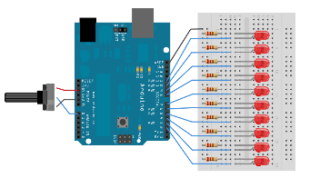
You can see how the LEDs are connected to the output terminals of the micrcontrollers. The microcontroller can then control the sequential lighting of the complete bar graph.