
How to Create a UART Receiver Interrupt Driver with an STM32F446 Microcontroller Board in C
In this article, we explain how to create a UART receiver interrupt driver with an STM32F446 microcontroller board in C.
UART stands for universal asynchronous receiver transmitter, and it is often used to transmit or receive data between a microcontroller and various components.
In our program, we will set it up so that we will allow for interrupts for our STM32 board to receive UART data from an outside device where both devices are set up for UART communication with one another.
When the secondary device sends information to our host device, the STM32 board, an interrupt is created and halts any program currently running (assuming the interrupt has a higher priority) and runs the UART interrupt service routine.
In this code, we are not actually going to code for priority, but this can be easily done. If you want, you can take a look at the article, How to Set the Priority of an External Interrupt with an STM32 board in C.
So previously, we created a program on, How to Receive Data with the UART Communication Protocol with an STM32F446 Board in C. If you need to, please familiarize yourself with how to receive data with the UART communication protocol first without interrupts, because we will not be going over all the code as extensively as this article. The explanations in this article are specifically more for just adding interrupts for UART communication to receive data.
So we take this program and modify it a bit by enabling the USART RXNEIE interrupt bit in the USART Control Register 1 and then enabling the interrupt for UART on the processor side, meaning for the Cortex-M4 processor.
We do both of these tasks within the the code to initialize the UART communication.
The next thing we need is an interrupt service routine for UART communication. This is the function our code will execute when an interrupt does occur. In this case, we will display the character pressed on a keyboard in the live expressions section of the STM32 software and if the character pressed is 'y', the green LED onboard will turn on. It's simply to demonstrate how we can run code through an interrupt service routine.
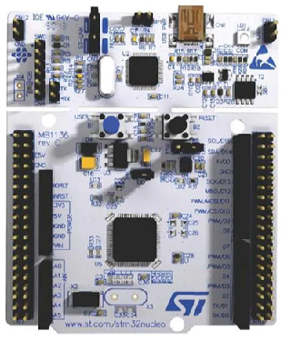
For this program, we will just be using the USART2_TX and USART2_RX pins, pins PA2 and PA3, respectively, for use of the UART communication. We don't actually have to do any connections at all.
The great thing about using the USART2 pins is that we can transmit or receive data using the UART protocol via USB.
So just connecting the STM32F446 board to your computer using a USB, you can allow for UART communication using a software. We will use the RealTerm software, which is a serial and TCP terminal for engineering and debugging.
We need 2 major code files in order for this code to work.
We need our header file, which contains many macros and structures that describe the various registers and needed values.
We then need our main C file, which contains the code that allows us to allow an interrupt to halt our program and execute the specific UART interrupt service routine.
Below is the header file that we will need for our code, which in this case is named,
stm32f407xx.h
So this header file contains all the definitions we need to create our main C file.
The contents of the main.c file is shown below.
So we have to add the prototype for the interrupt service. We do this with the line, void USART2_IRQHandler(void);
Within our main() function, we initialize the uart communication.
You can then see that we have an empty infinite while loop.
This shows you that our code is run through interrupts and not through the main() function.
Within the initializing function, we turn on the clock for the GPIO Port A, set PA5 as otuput, set PA2 to function as USART2_TX, set PA3 to function as USART2_RX, turn on the clock for USART2, initialize the baud rate for the UART communication, enable the transmitter and receiver (though we could only do the receiver, since we are not doing any transmitting in this program).
We then enable the USART RXNEIE bit, which enables interrupts for receiving data in UART communication. This is done through the line, pUSART2->CR1 |= (1 << 5);
Below is the USART Control Register 1.
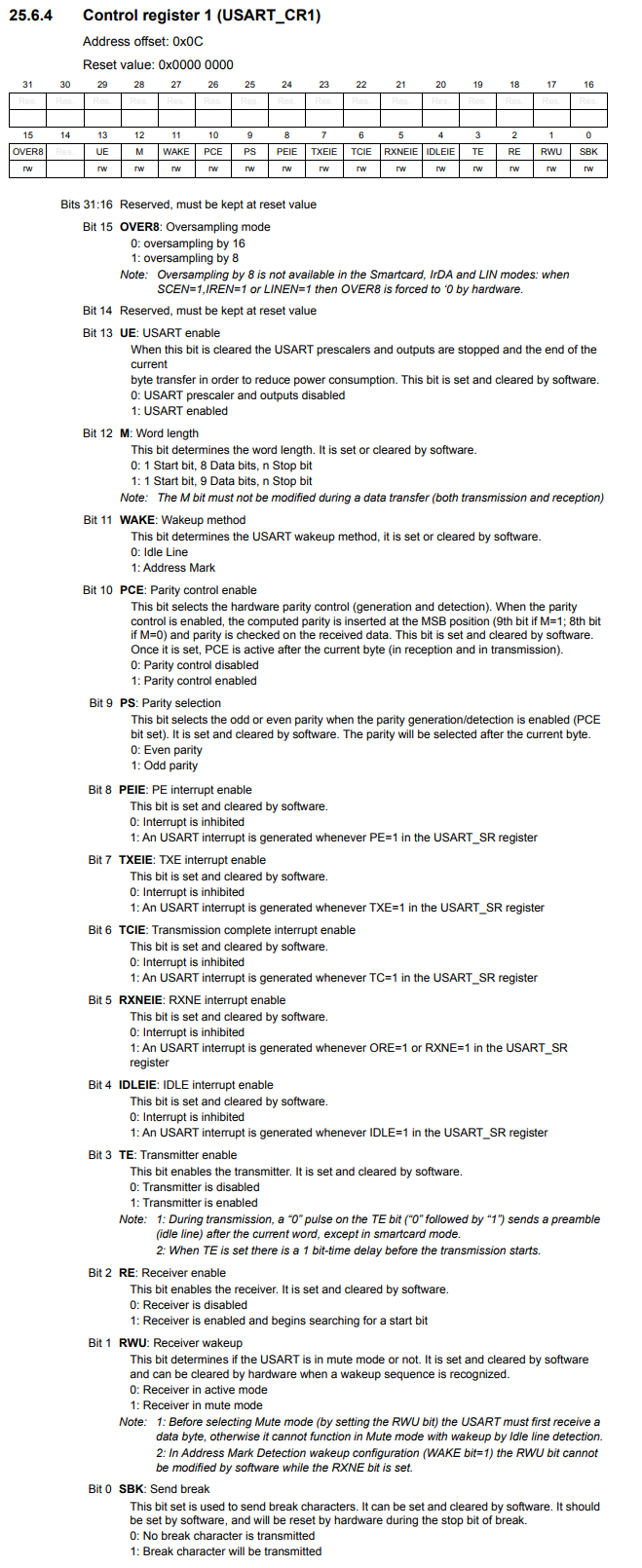
You can see that bit 5 is the RXNEIE bit, which allows for interrupts on the UART_RX connection for receiving data.
Next, we need to enable the interrupt for USART communication on the processor side, meaning the Cortex-M4 processor.
In order to do this, we need to gather information from both the microcontroller datasheet and the processor datasheet.
What we need from the microcontroller datasheet is to look at the datasheet for the position of the interrupt for USART2. If you do this for the STM32F446 microcontroller, you will see that this number is 38. So this is a very important number, because this is number will allow us to enable the USART2 interrupt.
Now we need to go to the processor datasheet for the Cortex-M4 processor.
There are a set of registers named the Interrupt Set-enable Registers (ISER), which allow us to enable interrupts.
This is shown below.
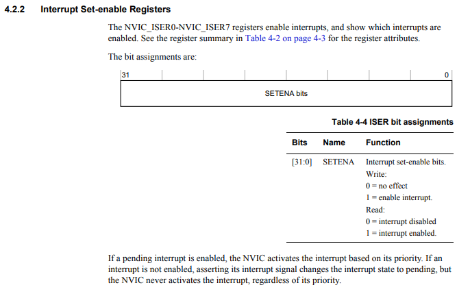
There are 8 of these registers in total, ISER0-ISER7.
Each register is 32 bits.
Each bit of a register controls a specific interrupt.
The reason that number 38 was so important for the USART2 interrupt is because that is bit in the ISER register that must be enabled to allow for USART2 interrupts.
We need to set HIGH bit 38 of the ISER register in order for USART2 interrupts to be enabled.
So in order to know which register and which bit to set high, we can use division to find the register and the modulus (%) to find the bit.
38/32 is 1, so we use the register ISER1.
38%32 is 6, so we set bit 6 of ISER1 HIGH to enable USART2 interrupts.
This is what we do in our code through the line, *pNVIC_ISER1 |= (1 << 6);
Lastly, we enable USART by setting bit 13 HIGH in the USART control register 1.
The next function is simply the function to compute the speed of communication of USART2.
Next we have our USART2 interrupt service routine handler.
So within this function, we use an if statement to check if any data has been sent and ready to be read. This we do with the USART status register, bit 5, which is the RXNE, which stands for, Read data register not empty.
We then copy the value to the data register.
If the key pressed is 'y', then the onboard LED connected to pin PA5 turns on. Else, if it is a different
key, it turns off.
And this is how we can code a UART receiver interrupt driver with an STM32F446 board in C.
Related Resources