
How to Create a Delay using a General-purpose Timer in an STM32F446 Microcontroller Board in C
In this article, we explain how to create a delay using a general-purpose timer in an STM32F446 microcontroller board in C.
General-purpose timers are so called because they can be used for a variety of purposes, including measuring the pulse lengths of input signals (input capture) or generating output waveforms (output compare).
We can use general-purpose timers to create delays in our program. This creates a delay through hardware, as the timer is an actual hardware device.
The STM32F446 microcontroller board has a number of general-purpose timers that consists of 16-bit and 32-bit auto-reload counter.
General-purpose timers on the STM32F446 board consists of timers 2 to 5.
Timers 2 and 5 are 32-bit timers that can be configured to be up, down, or up/down counters.
Timers 3 and 4 are 16-bit timers that can be configured also to be up, down, or up/down counters.
The important thing to remember about timers is that they are actual hardware devices. So when we create a delay with a timer, it is a hardware delay, as opposed to a software delay, for example, with a for loop and a software delay() function.
In this program, we will configure timer 2 to produce a delay of 1 second. We will use the on-board LED with this 1-second delay to toggle the LED on and off every 1 second.
So the first thing we should go over is how to calculate and set the correct registers in order to get the delay desired.
So the first thing you should know is that the hardware timers such as a general-purpose timer such as timer 2 functions off of the system clock of the microcontorller board. For STM32 boards, that is usually 16MHz, which is what the internal RC clock produces.
16MHz produces a time period of 1/16MHz= 62.5 nanoseconds, which is much faster than what we want.
In order to get a delay of 1 second, we need to bring the frequency of the clock down from 16MHz to 1Hz, which is to lower the frequency by a factor of 16MHz.
So the first method of doing this is using either one or more prescalers.
If you examine the clock tree of the microcontroller, there are various prescalers that emerge from the system clock, which can lower the signal. The timer 2 is located on the APB1 bus, so you can use the APB1 prescaler and lower the 16MHz clock signal significantly.
Next, there are several other prescalers you can use before the signal reaches the timer hardware device itself.
However, we won't take this approach in this program, although it is absolutely fine to do so.
Instead, we will simply set the prescaler on the timer prescaler register.
Below is the TIMx prescaler register.
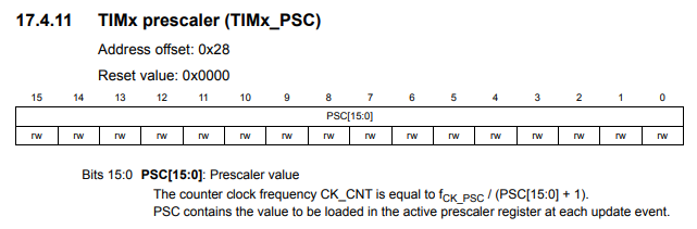
One important thing to notice is that this timer prescaler register is 16 bits in length. This means that it has a total size of 216, which is 65536. Therefore, we place into this register the decimal value anywhere from 0 to 65535 (0xFFFF).
What the value fed into this register does is it divides the clock signal fed into the timer by the number you give into it.
If we are using a 16MHz system clock and we use the maximum value that can given to this timer prescaler register, this would give us a value of, 16,000,000/65535= 244.14
However, we opt to go with a much more divisible number that doesn't give a decimal value.
We choose a prescaler value of 16000. 16MHz/16000 = 1000
So if we feed into this timer prescaler a value of 16000, this gives us a clock signal of 1000 or 1KHz.
So this is not good enough. Because in order to get a 1-second delay from a hardware timer, we need a frequency 1Hz. Therefore, we need to divide this signal by 1000 to get 1Hz. So how can we do this?
So there's another register called the timer auto-reload register.
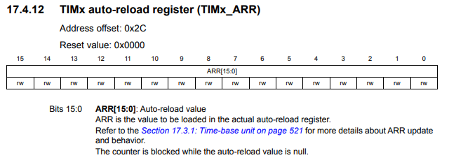
This register achieves the same effect as the prescaler.
If you load 1000 into it, it is as if we divided the signal by 1000 again to achieve a frequency of 1Hz.
Technically, according to the datasheet, the auto-reload register is preloaded. Writing to or reading from the auto-reload register accesses the preload register. The content of the preload register are transferred into the shadow register permanently or at each update event (UEV), depending on the auto-reload preload enable bit (ARPE) in TIMx_CR1 register. The update event is sent when the counter reaches the overflow and if the UDIS bit equals 0 in the TIMx_CR1 register.
So it's not technically division but mathematically it works as if it is.
Therefore, what we want to do is load 10,000 into this register to get 1Hz, which gives us a 1-second elay.
Just like the timer prescaler register, this register is a 16-bit register, so values can be fed into it ranging from 0 to 65,535.
So you now know how to create a hardware timer delay of any given length.
Therefore, let us now go into the code that creates a hardware timer delay of 1-second with timer 2 that allows us to toggle an LED on and off each second.
We need 2 major code files in order for this code to work.
We need our header file, which contains many macros and structures that describe the various registers and needed values.
We then need our main C file, which contains the code that creates our 1-second delay created by timer 2.
Below is the header file, which we name
stm32f407xx.h
The contents of the main.c file is shown below.
The first thing we must do is include the stdint.h header file and our stm32f446xx.h header file in our main.c file.
We create a function protoytpe for our tim2_init() function, so that the compiler knows its return type, what arguments it accepts, along with its data type.
We then have our main() function.
Because we want to turn on the onboard LED at pin PA5, we turn on GPIO Port A.
We then set pin PA5 as output.
We then initialize the timer. We will go over this code after.
We then have our infinite loop.
So within this while loop, we want the necessary time to pass for our hardware timer. This is why we have the following while loop statement, while(!((pTIM2->SR) & (1 << 0)));
This while loop will stay in the loop until the time for the delay of timer 2 has elapsed.
We do this by checking the value of bit 0, the Update interrupt flag, in the timer status register. If this bit is 0, no update occurred. If this bit is 1, an update interrupt is pending. Note that this bit is set by hardware when the registers are updated.
Our program will stay in the while loop until bit 0, the UIF bit, goes to 1, meaning the timer delay period has elapsed.
After this occurs, we want to clear this interrupt buy setting it back to 0.
We then toggle our LED.
By clearing the interrupt bit, bit 0, of the status register, we reinitialize the CNT register, which is the count register. The count process then commences again and goes infinitely in the while loop.
Now we go over the tim2_init() function.
So this function returns nothing and takes in nothing.
Within this function, the first thing we must do is enable the peripheral clock for the timer 2.
Since the timer 2 is connected to the APB1 bus, we enable the clock for this bus.
We then set the prescaler value, which we earlier determined would be 1600. But instead of feeding 1600 directly into it, we feed into it, 1600-1, because the value starts at 0.
We then set the auto-reload register, which we earlier determined would be 10000. Just like the other register, the first value starts at 0, so we feed into it, 10000-1
We next make sure the counter is previously clear so that there isn't any residual value left in there.
Below is the timer counter register.
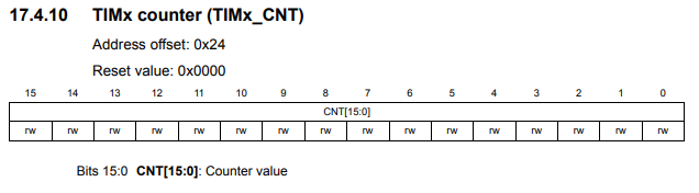
An important thing to know about this register is you don't have to manually configure it, as it will be updated automatically.
The only thing we do with this register is clear it.
Now that we have everything initialized for timer 2, all we have to do now is enable the timer.
This we do in the timer control register 1. This is shown below.
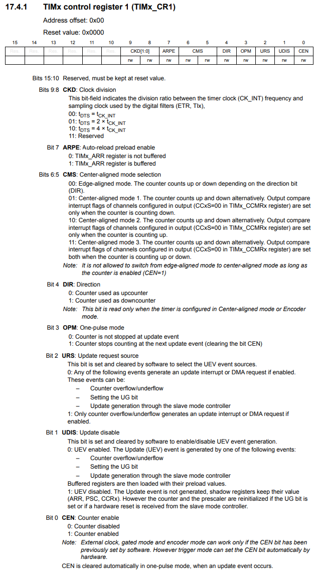
So the bit we need to set is bit 0, the CEN bit, which stands for Counter Enable.
We must enable the counter by setting this bit HIGH.
And that is all to get a hardware timer to work for an STM32 board.
Again, there's a variety of different ways to get the timer delay value, including adjusting the APB1 prescaler and/or the timer prescaler value, along with the auto reload register.
So there's a lot of different tools at your disposal.
So this is how to create a delay using a general-purpose timer in an STM32F446 board in C.
Related Resources