
How to Create a Time Delay for a PIC Microcontroller in C
In this article, we show how to create a time delay for a PIC microcontroller in the C programming language.
A time delay is something that is very important when working with embedded applications, because there are times you want a delay before something is begun.
For example, a user may press a button and an action occur maybe 3 seconds later or 5 seconds later .
Or a delay can be valuable in allowing some event to occur immediately, counting down a certain amount of time via a delay, and then shutting off the device. So delays can be used as timers for certain devices.
Time delays can also be used for breaks between processes. For example, a time delay in between an LED can make the LED blink on and off, on and off, repeatedly.
So time delays can be very useful and important for embedded applications.
If you're used to working with software like arduino, you may think you can just use something like, delay(1000), to create a 1-second delay in a program. However, this is not how it works when actually programming a real-life microcontroller.
If you use certain libraries and certain ready-made boards, there will simple functions like delay(), where you can put in the parameter in milliseconds and create a delay. But if you're doing yourself without the use of libraries and fully made microcontroller boards, this does not work at all. In fact, there isn't even any function named delay() to work with that is built-into C.
So in order to create a delay, we need to appreciate the underlying hardware and capabilities of our PIC microcontroller.
So, as you may know or you may not, standard PIC microcontrollers like the PIC18F4525 microcontroller can operate with a 8MHz oscillator. With a 8MHz oscillator, the PIC can carry out 2 million instructions in 1 second, as the actual clock the microcontroller uses runs at is a quarter of the oscillator.
For us humans that want to see something occur at a speed that the human eye can register, this is way too fast. We would have to slow it down, which is what a delay is for.
In order to create a delay, we must utilize the special timer registers of a microcontroller.
Timer registers do just what the name implies; they keep track of time, by counting from 0 to a certain a number of clock cycles.
By utilizing their ability to keep track of time, we can create time delays.
There are just 2 factors that control the length of a time delay, the number the timer counts to and the rate at which it counts.
The PIC18F4525 microcontroller has 4 timers: timer0, timer1, timer2, and timer3.
Each timer has a register that holds the current value of the timer and is incremented at the specified frequency, based on the microcontroller's clock, for that timer.
Each timer has a control register that can be used to specify how the timer should operate, meaning we can customize each timer.
Timer0 is the main timer for creating delays, whereas the other three timers have other uses but could still be used for delays if required.
The control register for timer0 is the T0CON register. It can customize the use of timer0.
To appreciate how to set up the timer, we need to appreciate the following.
- First, the clock, which produces the cycles that the timer counts, runs initially at a quarter of the oscillator. So if running an 8MHz oscillator, the clock runs at 2MHz, or 2 million instructions per second.
- Secondly, timer0 can be set up to be an 8-bit register or 16-bit register. If set to an 8-bit register, the timer counts up to 256 clock cycles (28), which is 0 to 255. After reaching 255, the counter goes back to 0. This is called rolling over. When timer0 first rolls over, a rollover bit will be set, and this can be used by the programmer if desired. Timer0 can also be set to operate as a 16-bit timer, which means it can count up to 65536, or 0 to 65535.
- We can also apply pre-scalars to the timer which will actually slow the rate at which the timer counts by dividing the clock frequency further.
Now that you have a basic idea of timers, let us go through an actual example of creating a 1-second time delay using an internal 8MHz oscillator.
So since timers operate in terms of fractions of a second, we want to set timer0 to be a 16-bit register. It is able to count up to a higher value being a 16-bit register vs an 8-bit register (256 vs 65536), so it can create a much longer delay. Thus, we use a 16-bit register.
Being that we are running on a 8MHz oscillator, the clock is running at 2MHz, which means that each clock cycle lasts 500 nanoseconds (1/2MHz= 500ns or 0.0000005 s).
Since timer0 has 65536 clock cycles and each clock cycle lasts 500ns, this means that a timer0 operating as a 16-bit register can count 32.768 milliseconds.
32.768 milliseconds is only 0.032768 of 1 second. Thus, the delay is not long enough.
We need to slow the timer down, which we can do by applying a pre-scalar.
Now is a good time for us to look at the T0CON register in the PIC18F4525 datasheet. This will show us how to initialize the bits to the T0CON register so that we can create a delay that will give us a 1-second delay.
This is shown below.
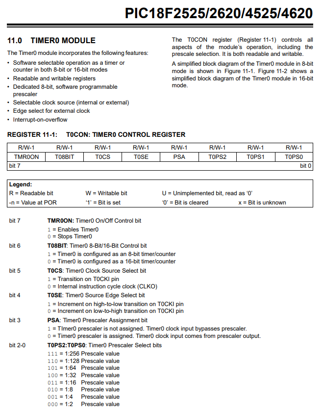
Let's now go over initalize this T0CON register.
We'll start with the most significant bit.
Bit 7, TMROON, enables or disables timer0. 1 Enables Timer0. 0 disables Timer0. If we want to enable it; thus, we feed it 1.
Bit 6, T08BIT, sets timer0 to either 8-bit or 16-bit operation. 1 sets timer0 as 8 bits. 0 sets timer0 as 16 bits. We want timer0 to be 16 bits; thus, we feed it 0.
Bit 5, T0CS, determines whether timer0 works with an external clock on T0CK1 pin or on the internal clock cycle (CLK0). Since we are using the internal clock in our example, we feed it 0.
Bit 4, T0SE, determines whether the timer0 operates on the negative or positive edge of the main clock signal. We'll make it operate on the positive edge, so we feed the pin 0.
Bit 3, PSA, allows for not further divide by selected divide rate or divided further by selected divide rate. Since we want the clock signal to be divided down by a prescalar, we feed this bit 0.
Bits 2-0 control the factor by which the clock is divided down. 256 creates the longest delay, so we select this; thus, we feed the bits 111.
This gives us a statement of, T0CON= 0b10000111, or in hexadecimal, T0CON= 0x87.
Even though we just went through a lot of parameters, in terms of calculations, only the last 3 bits matter, bits 2-0.
We selected 256 to divide the main clock by.
Again, we're using a 8MHz oscillator. The main clocks operates at a fourth of this, which is 2MHz.
2MHz/256= 7812.5 Hz.
So the main clock operates at 7812.5Hz per second.
Now doing the math, each clock cycle lasts 0.000128 seconds or 128 microseconds.
The math checks out, 7812.5 Hz(0.000128s)= 1.
So we know that 7812.5 clock cycles out of the 65536 is what is needed to get a 1-second delay.
As long as the count that the timer can do exceeds the delay we want, the time delay can be done.
Since we are using timer0 in 16-bit operation, which has 65536 clock cycles with each clock cycle lasting 0.000128 seconds, this translates into a time period of 8.388608 seconds. This is how much of a delay we will get if we used the full 65536 clock cycles.
We only want a 1-second delay, not a 8.388608-second delay.
So we just do simple algebra. What percentage of 8.388608 is 1.
The equation to solve for this is, 8.388608x=1. Doing the math, we get 0.11920928955.
So out of the 65536 clock cycles, we only need 0.11920928955. 65536(0.11920928955)= 7812.49999995.
It's just another way of calculating it.
So now we are ready to build our full program of giving us a 1-second delay.
In our program, we will turn on an LED for 1 second and then turn it off.
This is shown in the following code below.
So we do all the standard initializations.
Specifically in regard to the timers, since we are using timer0, we initialize the T0CON register, setting it to a hex value of 0x87.
We then set timer0 to a value of 0, starting it off from scratch.
While the timer is under 7812 clock cycles, we have the LED on.
Once these clock cycles have passed, we then turn the LED off.
And this is how we can create a time delay for a PIC microcontroller in
C.
Related Resources
How to Set the Ports of a PIC Microcontroller in C