
How to Create an ADC Interrupt Driver with an STM32F446 Microcontroller Board in C
In this article, we explain how to create an ADC interrupt driver with an STM32F446 microcontroller board in C.
With an ADC interrupt driver, we can have an ADC interrupt the program once the end of conversion has been reached for a particular analog-to-digital conversion.
In our program, we will have an ADC interrupt driver set to continuous sampling and that will show the ADC value with each interrupt.
Previously, we created a program on, How to Perform Analog-to-Digital Conversion with an STM32 Board in C. If you need to, please familiarize yourself with how to perform analog-to-digital conversions before using interrupts, because we will not go over that code as extensively; we will simply be going over how to turn that code into it being done with an interrupt driver.
So we take this program and modify it a bit by enabling the EOCIE interrupt bit in the ADC Control Register 1 and then enabling the interrupt for ADC on the processor side, meaning for the Cortex-M4 processor.
The next thing we need is an interrupt service routine for the ADC. This is the function our code will execute when an interrupt does occur. In this case, we will show the ADC value with each interrupt. It's simply to demonstrate how we can run code through an interrupt service routine.
We need 2 major code files in order for this code to work.
We need our header file, which contains many macros and structures that describe the various registers and needed values.
We then need our main C file, which contains the code of the ADC interrupt driver.
Below is the header file that we will need for our code, which in this case is named,
stm32f446.h
So this header file contains all the definitions we need to create our main C file.
The contents of the main.c file is shown below.
We will now go over the code.
So we place the prototypes of our functions into our code.
We create a global variable, adc_value. We will use this variable to store the value of the ADC value from our program.
We then have our main() function.
Within this main() function, we initialize the ADC through the pa1_adc_interrupt_init() function.
We then start the ADC conversion process through the adc_start_conversion() function.
We then have an empty while loop.
We then have our pa1_adc_interrupt_init() function.
We then enable the clock for ADC1 and of the GPIO Port A. We then set pin PA1 to be an analog pin.
We then enable the ADC end-of-conversion interrupt.
This is found in the EOCIC interrupt bit, bit 5, of the ADC control register 1.
This is shown in the register below.
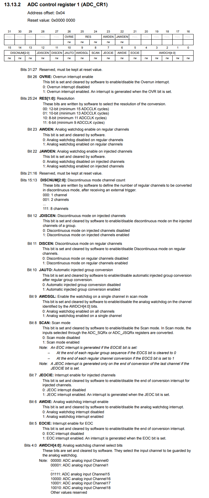
So you can see that Bit 5, the EOCIE bit, is the interrupt enable for EOC (End of Conversion). This bit is set and cleared by software to enable/disable the end of conversion interrupt. We enable this bit by setting it HIGH. We then later clear the bit in another register, the ADC status register, bit 1, the EOC bit, by setting that bit HIGH after an interrupt occurs.
After enabling the EOC interrupt on the microcontroller side, we then have to enable the interrupt on the processor side on the NVIC. This is for the Cortex-M4 processor of the STM32 microcontroller.
We do this in the ISER (Interrupt Set enable register).
Before we go to this register, we need one important piece of information from the microcontroller's datasheet, the IRQ number of the ADC interrupt.
You would obtain this from the vector table, which has the IRQ numbers for each type of interrupt.
Looking up the interrupt for ADC, it is found that the interrupt has an IRQ number of 18. This will be found on the column of the vector table named Position.
Now we need to go to the processor datasheet for the Cortex-M4 processor.
There are a set of registers named the Interrupt Set-enable Registers (ISER), which allow us to enable interrupts.
This is shown below.
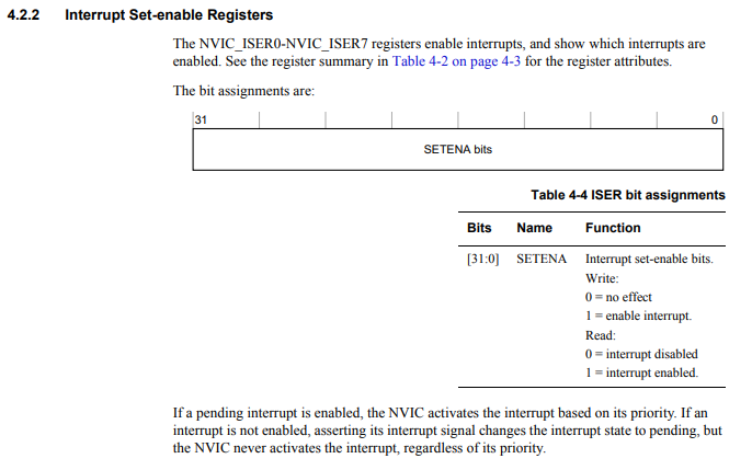
There are 8 of these registers in total, ISER0-ISER7.
Each register is 32 bits.
Each bit of a register controls a specific interrupt.
The reason that number 18 was so important for the ADC interrupt is because that is the bit in the ISER register that must be enabled to allow for ADC interrupts.
Now that we know the IRQ number is 18, this means we have to set the 18th bit of the ISER0 register to a HIGH value.
If the interrupt value is greater than 31, this would go to the next ISER register.
Interrupts from 0 to 31 would be in ISER0.
Interrupts from 31 to 63 would be in ISER1.
Interrupts from 64 to 95 would be in ISER2.
So we set the ADC interrupts on in the Cortex-M4 processor by the following line, *pNVIC_ISER0 |= (1 << 18);
We then make the first ADC sampling start at channel 1 by the line, pADC1->SQR3 |= (1 << 0);
Because we are only sampling from a single device, we specify the conversion sequence length as 0. If we were sampling from multiple ADC devices, we would have to specify this here.
We then enable ADC1 by the following line, pADC1->CR2 |= (1 << 0);
We next have our adc_start_conversion() function.
Since we want continous sampling, we specify this in the ADC Control Register 2 by setting bit 1, the CONT bit, to HIGH.
We then start the ADC conversion process by setting bit 30, the SWSTART bit, to HIGH.
Lastly, we have our interrupt service routine.
This is the function that will be executed when there is an interrupt.
First, in this function, we check to see if the EOC flag in the ADC status register is HIGH. If it is, we clear the bit to reset it. Then we save the value from the ADC DR (Data Register) intot the adc_value variable. We then can print this out using the printf() function, or you can check the value in the DR register if you are running the code in debug mode.
When you run this code, you can place the adc_variable into the Live Expressions tab of the STM32 software
and then run the code in debug mode. Even without connecting any ADC device to pin PA1, it will check due to random noise
and fluctuations. You should see this value constantly changing.
And this is how we can create an ADC interrupt driver with an STM32F446 board in C.
Related Resources