
How to Create an I2C Driver with an STM32F446 Microcontroller Board in C
In this article, we explain how to create an I2C driver with an STM32F446 microcontroller board in C.
An I2C driver allows us to communicate with a device that uses the I2C communication protocol.
In our example, we will use our STM32 board as the master device and communicate with a slave device, a DS1307 real time clock. We will get information from this slave device to know its position.
The I2C, which stands for Inter-Integrated Circuit, communication protocol is a two-wire interface protocol that has 2 lines of transmission, SCL and SDA.
SCL is the serial clock line, which is used for synchronizing data transfer between the master and salve.
SDA is the serial data line, which is used to transfer the data.
The operation modes of the I2C protocol is either Master Transmitter, Master Receiver, Slave Transmitter, or Slave Receiver.
With the I2C protocol, transactions are initiated and completed by the master device.
All messages have an address frame and a data frame.
Data is placed on the SDA line after SCL goes LOW, and it is sampled after the SCL line goes HIGH.
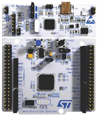
In our sample program, we will use an STM32 board with a DS1307 real time clock.
Because the DS1307 real time clock, as pretty much all components need, require power, we need to connect the component to +5V and GND, in order to power it.
Because we are using the I2C communication protocol, which is a two-wire protocol, we need to make 2 connections, SCL and SDA, to establish I2C communication between the STM32 board and the DS1307 real time clock.
So, in total, 4 wire connections are needed between the STM32 board and the real time clock.
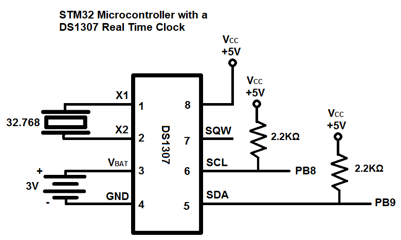
The circuit schematic for the circuit we will build is shown below.
So, after this hardware connection is made, the only thing we need now is the software to execute on the board.
We should then be able to read the time that the real time clock gives us.
So below is the code needed in order to run this real time clock circuit.
Before we go directly into our main C code, there are some supporting files we need, including register maps and macros needed.
Below we have the stm32f446.h file, which contains many register maps (including for the
I2C register) and macros needed for the software program.
So we can now go to our main.c file.
So this code is somewhat long, so we will break it down to make it understandable.
So we first include the header files we need.
We then have a list of the function prototypes, so that the compiler knows about them, as in what they return and what parameters they take in, as well as the parameter types.
We then define a number of variables, which we use in our program. We will get back to these, as well as the main() function.
Instead now we skip ahead to the I2C1_init() function, which initializes the I2C communication protocol so that we can use it to communicate with the ADXL345 accelerometer device.
So we can start taking a look at charts.
Below is the alternate function mapping of GPIO Port B for an STM32F446 microcontroller board.
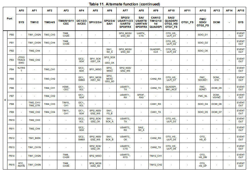
So you can see that in AF4, pin PB8 functions as I2C1_SCL and pin PB9 function as I2C1_SDA.
This is important to know because these are the 2 pins that we use for I2C communication.
I2C has 3 channels in an STM32F446 board, I2C1, I2C2, and I2C3. I2C1 is the one we are using in this case.
So because we are using GPIO Port B, we must enable the clock for GPIOB.
After this, we must enable the clock to I2C1. I2C1 (as well as I2C2 and I2C3) are all connected to the APB1 bus.
To turn on the clock for I2C1, we write a 1 to bit 21 of the APB1ENR register.
We then must configure pin PB8 to be in alternate function mode. This we do by writing 0b10 to bit 16 to the GPIOx_MODER register.
We then go to the AFHR (Alternate Function High Register) and we write 0b0100 to bit 0 in order to put pin PB8 in AF4, which makes it act as I2C1_SCL.
We then do the same for pin PB9, putting the pin in alternate function mode with the MODER register and then setting the mode to AF4 with the AFHR register.
An important thing to remember with the I2C communication protocol is that the various pins must be in open drain configuration. I2C does not operate with push-pull mode. Therefore, we must set this for pins PB8 and PB9 in the OTYPER register.
Another important thing for the I2C communication protocol is having pull-up resistors for each of the pins, SCL and SDA. You don't have to physically connect these lines to pull-up resistors. It is sufficient to connect these pins to pull-up resistors in software. We do this in our code with the PUPDR register.
Next, we begin setting bits of the I2C registers to configure I2C settings.
Below is the I2C control register 1.
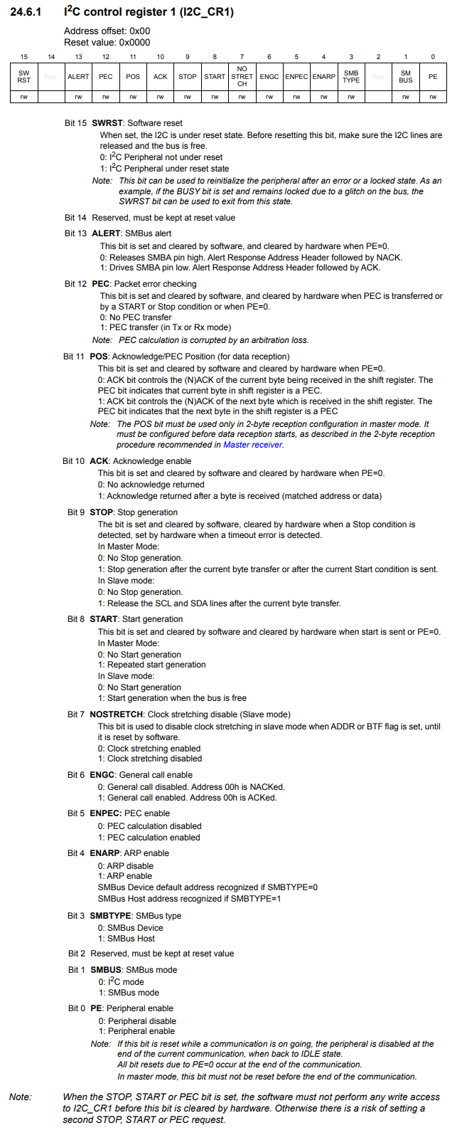
First, we must reset I2C1 and then come out of the reset state. This is done by setting bit 15 to 1 and then clearing it and setting it back to its default state of 0.
We then must set the clock frequency of I2C1 to 16MHz. We do this in the control register 2.
This register is shown below.
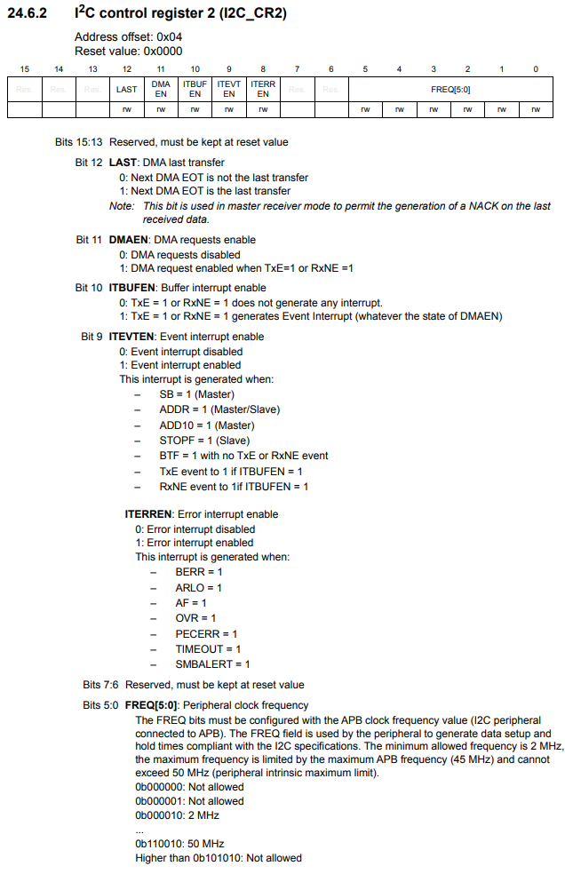
Bits 5:0 are the bits that set the peripheral clock frequency. Since we want to set the frequency to 16MHz, we have to write out the binary equivalent of 16 to these bits, which is 010000. Therefore, we feed 0b010000 into these bits to get a clock frequency of 16MHz. Each bit signifies the frequency in MHz. So if we set this bit to a value of 2, this would be a frequency of 2MHz. According to the datasheet, the minimum allowed frequency is 2 MHz and the maximum frequency is limited by the maximum APB frequency (45 MHz) and cannot exceed 50 MHz (peripheral intrinsic maximum limit).
To set the I2C clock to standard mode (100KHz), we feed the value of 0b01010000 into the I2C clock control register (I2C_CCR).
We then must set the rise time of the clock signal, which is how long it takes for a clock to go from a LOW logic state to a HIGH logic state. According to the datasheet, in standard mode, the maximum allowed SCL rise time is 1000 ns. We simply set our value to 17.
Lastly, we can then enable the I2C1. We do this by setting bit 0, the peripheral enable bit, to 1. This turns on the I2C communication protocol.
So we then have our next function, I2C1_byteRead().
This function takes in 3 parameters: slaveadress, memoryaddress, and data.
We create a volatile integer variable named tmp.
The first thing we must do is wait until I2C1 is no longer busy.
We can check this with the Busy bit, bit 1, on the I2C status register 2.
This register is shown below.
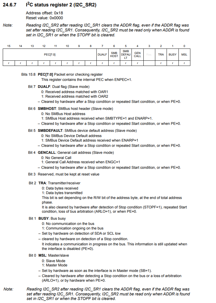
As long as the bit is 1, there is ongoing communication on the bus. We must wait until this bit is cleared to 0 before we continue on with our program.
Once the bus is not busy, we generate a start condition. This is done by setting the start bit, bit 8, of the control register 1 to HIGH.
Then we must wait until the start flag is set.
We then attempt to communicate with the slave device. WE do this by transmitting the address of the slave device and then we must specify whether we are looking to write to the slave device or read from the slave device. When we are looking to make contact with a slave device, it is always a write.
When we are attempting to communicate with a slave device, we write the address to the data register.
The data register is shown below.
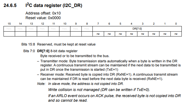
Notice how this register only takes a byte of data (8 bits). Slave addresses can never be longer than 8 bits in order for the master to be able to identify the slave it wants to communicate with.
So after we write this slave address to the data register, we must then wait until the address flag in the status register 1 to be set.
The I2C status register 1 is shown below.
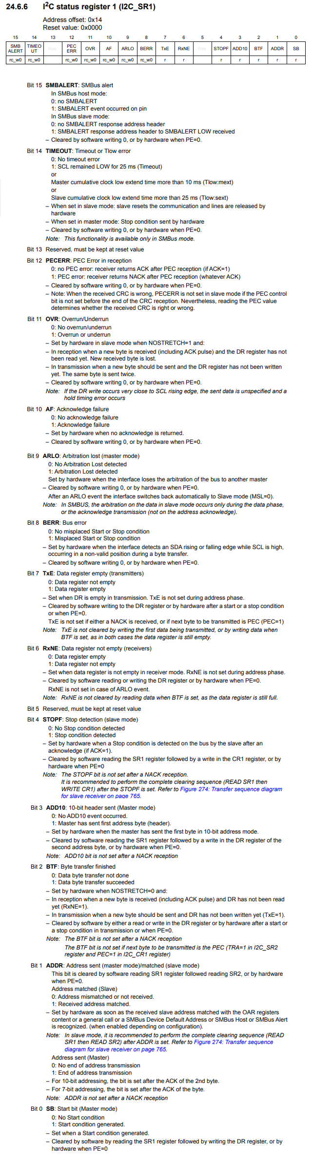
This address bit is very important, as this signals that the master has successfully communicated with the slave device. If the
If the address bit sets and is then cleared, then successful communication has been made from the master to the slave device.
The 2 devices can then do more commmunicating later.
If the address bit does not set, this signifies that the master was not able to successfully communicate with the slave device. This could be because the address is incorrect or there is some incorrect hardware setup such as no pull-up resistors to VCC or incorrect resistor values. It's best to use resistors between 2KΩ-4KΩ. The internal pull-up resistors used in software are around 40K, which is too high for I2C communication. So there are a variety of different reasons why the address bit wouldn't set, so troubleshooting is required.
We then clear the address flag by the line, tmp= pI2C1->SR2;
So the slave address is the fixed address created by the manufacturer, so that a master device can identify it. You can see it as the external address of the slave device.
The memory address is the address of the register we want to read from or write to in the slave device.
We send the memory address (which is the data register of the slave device) we wish to read from or write to by writing this memory address by sending this address to the data register, just like we did with the slave address.
We then must wait until the transmitter is empty, which we can check by checking the TxE bit, bit 7, of status register 1. If the value of the TxE register is 1, then the data register is not empty, which means transmission is still in progress. We must wait for the bit value to be 0, which means the data register is empty which means transmission is complete.
We must then generate a restart condition and wait until the start flag is set, as we did previously.
We then transmit the slave address this time with read. We then wait until the address flag is set.
We then disable the acknowledge bit.
We then clear the address flag.
We then generate a stop condition.
We then wait until the RXNE flag to be cleared, meaning the data register is empty.
We then read the data from the data register.
We then have a delay function.
Now we go back to our main() function.
So we run the I2C1_init() function in order to initialize the I2C1 communication.
We then turn on the clock for GPIO Port A, because we are going to turn on the LED at PA5. We set pin PA5 as output.
We then have our infinite while loop.
In this while loop, we have simple code.
We use the I2C1_byteRead() in this infinite loop, because we are always going to continouously be reading from this register.
The I2C1_byteRead() function takes in 3 parameters.
The first parameter is the slave address, so that the master (the STM32 board) can identify that the slave device (the DS1307 real time clock).
The second parameter is the memory address, which in this case is 0. What 0 represents is the second data of the real time clock.
The third parameter is the data itself.
This program has the effect of creating a blinking LED.
And this is how a very basic program of how I2C communication works with an STM32 board and a slave device that uses the I2C protocol.
This I2C driver program serves as an example that can be applied to any I2C slave device, such as an accelerometer, humidity sensor, or any other type of I2C device.
And this is how to create an I2C driver with an STM32F446 microcontroller board in C.
Related Resources