
How to Enable a GPIO Pin to Function as the Source of an External Interrupt with an STM32F407G Microcontroller Board in C

In this article, we explain how to enable a GPIO pin to function as the source of an external interrupt with an STM32F407G microcontroller board in C.
With the GPIO port pin in this configuration, we can cause any various event on this pin to trigger an interrupt service routine (ISR), which exits the program and runs this interrupt function.
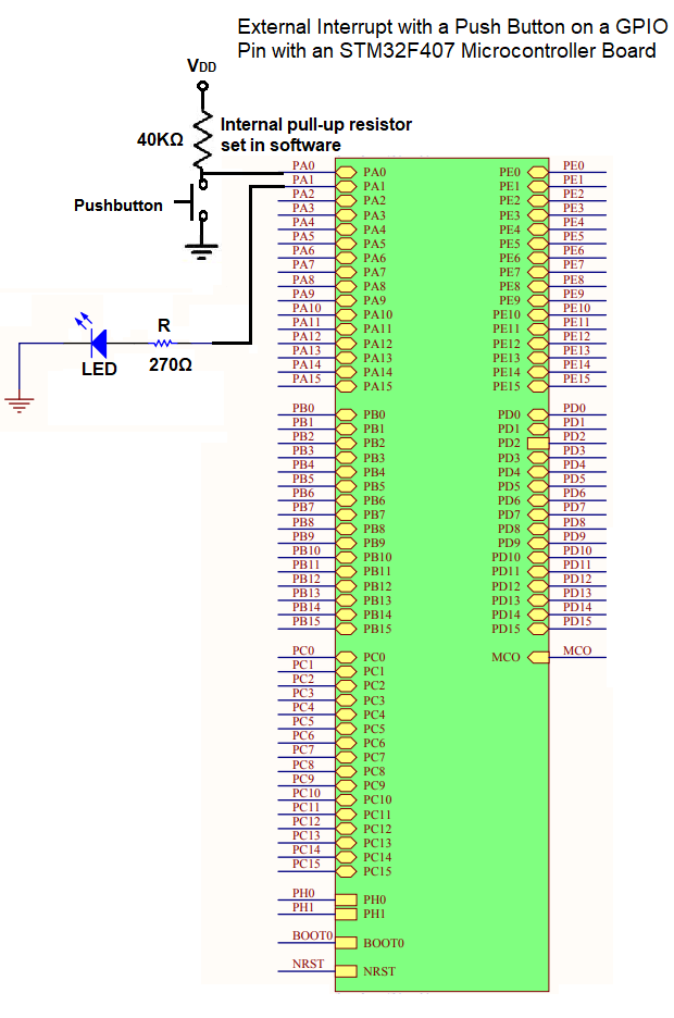
In this project specifically, we configure GPIO port A pin 0 to function as the source of an external interrupt. We connect a push button to this pin. We connect the push button to a pull up resistor to VDD. When the push button is pressed, this HIGH voltage state transitions to a LOW voltage state. With the interrupt being triggered with a falling edge signal, the interrupt gets triggered. We then connect an LED to GPIO port A pin 1, which will toggle the LED with each button press.
This project serves to teach you how external interrupts work and specifically how to configure GPIO pins to function as sources of external interrupts.
External interrupts can appear as well from other pins, not just general-purpose GPIO pins.
External interrupts can be triggered from GPIO pins in alternate function mode such as SPI, I2C, UART, USB, etc.
In this article, we specifically deal with configuring GPIO pins to function as sources of external interrupts.
So let's now talk about how this works.
So STM32 boards come with multiple GPIO pins that have 16 pins each. This is the case with the STM32F407G board.
Any of the 16 pins of any GPIO port can function as the source of an external interrupt.
Below is a diagram that helps to illustrate how this process works.
We will explain it in detail below.
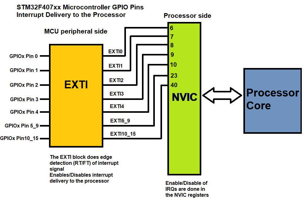
So to the leftmost of the diagram, you see the GPIO pins.
Next, you see a module named EXTI, which stands for the External interrupt/event controller.
This controller can select whether the input is an interrupt or event, and whether the event is triggered by a rising edge, a falling edge, or both.
This controller also has an interrupt mask register, which allows for the enabling or disabling of the interrupt delivery to the processor.
You then see that there is a module labeled NVIC. The NVIC stands for nested vector interrupt controller, and it is present within the actual processor (the Cortex-M processor) of the microcontroller. This is because interrupts are ultimately handled by the processor. They originate from peripheral components such as the GPIO pins on the microcontroller board (outside of the processor) but they have to be processed by the NVIC register in the core processor of the board.
You can see numbers on the NVIC register. These are referred to as IRQ (interrupt request) values.
We must enable the appropriate IRQ for the corresponding GPIO pin we are sourcing the external interrupt from.
For GPIO pin 0, this is IRQ number 6.
For GPIO pin 1, this is IRQ number 7.
For GPIO pin 2, this is IRQ number 8.
For GPIO pin 3, this is IRQ number 9.
For GPIO pin 4, this is IRQ number 10.
For GPIO pins 5 to 9, this is IRQ number 23.
For GPIO pins 10 to 15, this is IRQ number 40.
Pins 5 to 9 are grouped together, as well as pins 10-15. This is because they all use the same IRQ number.
Once we enable the IRQ number via the Interrupt Set-enable register of the Cortex-M processor, the processor will process the interrupt from the peripheral component on that line.
Once an interrupt is performed on that line, a pending register will be set, which will then jump to the ISR function for that interrupt line, and the action that we coded will be performed for that interrupt request.
So that is basically how external interrupts work for GPIO pins with STM32 boards.
Again, we will be using GPIO port A pin 0 as the source of an external interrupt. We will connect a push button to this pin which is pulled up to VDD via an internal pull-up resistor. We then configure the interrupt to be triggered during a falling edge. This will then cause the ISR to be executed and our function to be executed.
The circuit we will build is shown in the diagram below.
We need 2 major code files in order for this code to work.
We need our header file, which contains many macros and structures that describe the various registers and needed values.
We then need our main C file, which contains the code to execute the ISR when an external interrupt is triggered (by pushing down the push button).
Below is the header file that we will need for our code, which in this case is named,
stm32f407xx.h
So this header file contains all the definitions we need to create our main C file.
The contents of the main.c file is shown below.
The first thing we must do is include the header file in our main.c file.
We next have our main function.
In our main function, the first thing we do is enable the peripheral clocks for the GPIO Port A and the SYSCFG register. The GPIO Port A pin 0 is where we will have the source of our external interrupt through a push button connected to it. We must turn on the SYSCFG register because it selects pin 0 to be an external interrupt.
So in order to use a GPIO pin as an external interrupt, we must set it in the SYSCFG register. This process is a little involved. To find an another article dedicated to this, see How to select a GPIO pin to be the source input of an external interrupt in an STM32F407GG Board in C.
To set GPIO port A pin 0 as the source of an external interrupt, we set register EXTICR1 bits 0-3 as 0000.
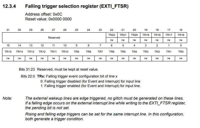
So what we do next is make pin 0 of the FTSR register a logic HIGH, which makes the interrupt triggered at the falling edge of the signal.
This EXTI FTSR register is shown below.
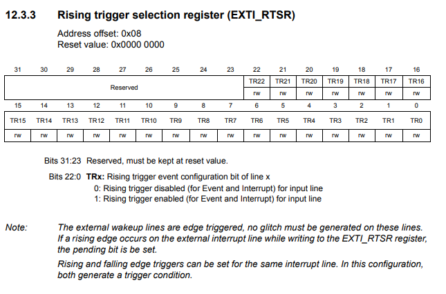
We want to make sure that rising edge isn't triggered also, so we clear the 0 bit of the RTSR register.
The EXTI RTSR register is shown below.
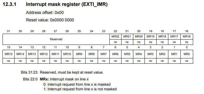
We then enable the interrupt by setting pin 0 to a logic HIGH in the IMR register, or interrupt mask register. The interrupt mask register allows us to enable or disable external interrupts for the GPIO pins.
The EXTI IMR register is shown below.
Next we have to enable the interrupt for EXTI0 on the processor side. We do this by setting the appropriate bit in the Interrupt Set-enable register. So we just before enabled the interrupt on the microcontroller peripheral side. Now in order for the processor to take in the interrupt, we must enable it on the processor end. We do this by modifying the NVIC_ISER0 register; we write a logic HIGH to the 6th bit of this register.
The Interrupt Set-enable Registers are shown in the diagram below.
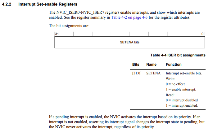
One thing that is important to know that for the Interrupt set-enable registers is that there are 8 of these registers in total, ISER0-ISER7.
Each register is 32 bits, which means for the 8 registers, they compose 256 bits, which covers all possible 240 external interrupts that the Cortex-M4 processor can process.
Each bit refers to 1 of the possible external interrupts corresponding to the IRQ number of the interrupt.
So for the first register of the Interrupt Set-enable registers, ISER0, this addresses the external interrupts IRQ 0 to IRQ 31.
ISER1 corresponds to interrupts IRQ 32 to 63.
ISER2 corresponds to interrupts IRQ 64 to 93.
In our case, we want to enable the external interrupt, IRQ 6, which is ISER0 register bit 6; so we set this bit to 1.
The next step is optional.
In the next step, we set the priority of the external interrupt.
This is important if you have multiple interrupts and want to prioritize one or some over others.
This is done on the processor side with the interrupt priority registers. The interrupt priority registers consist of 60 registers in total that can set the interrupt priority of 240 external interrupts based on the IRQ number of the interrupt.
If you look at the vector table for the STM32F407G microcontroller in its datasheet, you will see that there are only 82 external interrupts possible for this microcontroller.
So it doesn't use the full capability that the processor can offer.
So each of the 60 registers are 32 bits.
This is shown in the diagram below.
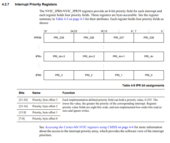
Each register is divided into 4 8-bit sections to cover the 240 possible external interrupts.
These registers are IPR0 to IPR59.
Register IPR0 sets the priorities for IRQ 0, IRQ 1, IRQ 2, and IRQ 3.
The first 8 bits are for IRQ 0.
The next 8 bits are for IRQ 1.
The next 8 bits are for IRQ 2.
And the last 8 bits of the 32 bits are for IRQ 3.
Register IPR1 sets the priorities for IRQ 4, IRQ 5, IRQ 6, and IRQ 7.
And so on.
To know which register you need to be working with when dealing with a particular IRQ number, take the IRQ number and divide it by 4. In this case of IRQ 6, 6/4 = 1. Therefore, we need to deal with register IPR1.
Now in order to know which 8-bit section you need to modify, you take the IRQ number and use the modulus operator on it. 6%4= 2. Therefore, we write to the 3rd 8-bit section of the IPR1 register.
Being that we are working with IRQ 6 in our code, we need to modify the register IPR1 in bits 16-23.
Let's now break down the formula, *(pNVIC_PR_BASEADDR +(IRQ_NO_EXTI0/4)) |= (2 << (8 *(IRQ_NO_EXTI0 % 4) + 4));
So we defined the base address of the priority register in the macro, pNVIC_PR_BASEADDR
The base address is, 0xE000E400U
The IRQ number is 6; therefore, 6/4 = 1 in integer mathematics. We add 1 to the base address, which adds 4 bytes to the address. This gives us the address of 0xE000E404U, which is the address of register IPR1.
So now the pointer variable is referring to register, IPR1.
We then set the priority value of 2 to the 8 times the value of 6%4, and then we add 4 to this value.
To understand this, multiplying the value by 8 gives us the start of the 8-bit section of the register.
The reason we add 4 to this register is that the value of the priority is set by setting the upper 4 bits of the 8 bits. The lower 4 bits are ignored.
The priority levels we can set ranges in value from 0 to 15. The lower the number, the greater the priority, so a priority value of 0 is the highest priority.
15 in binary is 4 digits, 1111
Therefore, only 4 bits are needed to set the priority and it is the upper 4 bits of the 8-bit section.
So after this, we set GPIO port A pin 1 to be an output. We do this by writing a 1 to bit 2 of the GPIO mode register.
We set GPIO port A pin 0 to be of high speed.
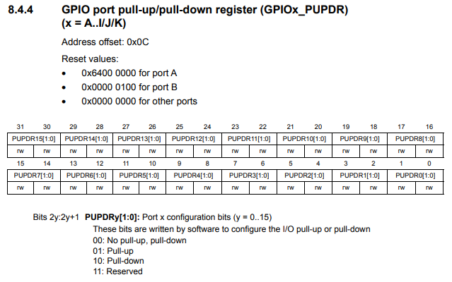
We then enable the internal pull up resistor on GPIOA port A pin 0. This makes the push button pulled up to VDD when not pressed. When it is pressed, it will be brought down to VSS, or GND.
This GPIO port pull-up/pull-down (PUPDR) is shown in the diagram below.
So with an internal pull-up resistor, we do not have to connect an external resistor, saving parts.
We then have the program loop forever with the statement, while(1);
After this main() function, we then create a delay() function, because we need to eliminate debouncing with the button press. We can do this in software. In hardware, you could use capacitors. In software, you just create a delay() function. The delay() function we create gives a delay of about 400ms or 4/10th of a second. This prevents multiple keypresses from being detected within a short period of time.
Next, we have our interrupt service routine, or ISR.
This is what is done when the external interrupt is triggered.
We use the delay() function to prevent debouncing.
The next thing we have to do is clear bit 0 in the pending register.
The EXTI pending register is shown below.
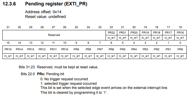
So when an external interrupt is triggered by the falling edge of the signal, what happens is the pending register of the EXTI registers is set to 1.
What we must do now is clear this bit. If this bit is not clear, the external interrupt, once triggered, stays triggered. To allow the interrupt to execute only once, we must clear the bit in the interrupt service routine. The bit is cleared by setting the bit to 1.
Lastly, we use XOR logic to toggle the LED connected to GPIO port A pin 1 with the line, pGPIOA->ODR= pGPIOA->ODR ^ (1 << 1);
So running this program, the LED will toggle from on to off or off to on with each button press.
Each button press triggers an external interrupt.
So this is how to enable a GPIO pin to function as the source
of an external interrupt with the STM32F407G microcontroller board in C.
Related Resources