How to Build a Half Wave Rectifier Circuit
To build a half wave rectifier circuit, the only electronic components that you need are a diode and a resistor.
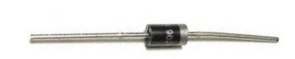
The diode can be any rectifier diode such as a 1N400X diode and any resistor in the 470Ω range.
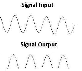
When you input an AC voltage signal into this circuit, only the positive half of the AC voltage signal will show. The diode allows the AC signal to go through unimpeded on the positive half of it and doesn't allow the negative portion to go through. The negative portion remains constant at 0.
This is because diodes essentially function as one-way valves. They only allow signal flow through the positive side of the diode to the negative side (anode to cathode), but not from the negative side to the positve side (cathode to anode).
Circuit
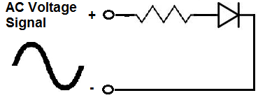
You can input an AC signal into this circuit from a function generator.
If you were to place the probe of an oscilloscope before the resistor and then one after the resistor, you would see these two waveforms: