
How to Read a Digital Voltage in Circuitry
In this article, we explain how to read a digital voltage in circuitry.
This means in a circuit, we'll be able to read whether the digital voltage is 0V or its peak voltage such as 5V or 6V.
Before we go into various ways of how to read a digital voltage in a circuit, let's first go over a digital voltage.
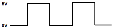
So a digital voltage is a voltage that can be in only 1 of 2 states. The voltage can either be entirely off or LOW at 0V. Or the voltage can be entirely ON or HIGH at the peak voltage. Let's say the voltage of the signal goes to 5V. This means the digital voltage can either be 5V or 0V.
This is in contrast to an analog voltage which can be take on an infinite range of values anywhere from the trough (lowest point) of the signal to the peak (highest point) of the signal.
Reading an analog voltage is a totally different process. Normally to read an analog voltage you need either a microcontroller that has an analog-to-digital converter or you need an analog-to-digital converter chip itself to read the voltage.
But in this circuit, we're concerned about how to read a digital voltage in a circuit so that we can know whether the digital voltage is HIGH or LOW. And then based on that, we can make the circuit perform an action based on the state of the digital signal.
So now that you know a digital voltage signal can either be HIGH (ON) or LOW (OFF) and only in 1 of those 2 states, let's go over ways now how we can read this digital voltage.
And there's many ways of reading a digital voltage in a circuit.
Reading a Digital Voltage with a Voltage Comparator Chip
So one of the ways we can read a digital voltage in a circuit is through the use of a voltage comparator chip.
A voltage comparator chip is a chip that can measure voltage.
There are many different voltage comparator chips available in the electronics chips market.
There is the LM311, LM339, LM393, and you can even use a general-purpose op amp chip such as the LM741 op amp to function as a voltage comparator.
So how does this work?
How a voltage comparator can read a digital voltage is you set a reference voltage to the noninverting terminal of the comparator. Then you place the digital voltage you want to read into the inverting terminal of the comparator. If voltage at the inverting terminal is greater than at the noninverting terminal, then the output turns on.
The voltage comparator measures the voltage at the inverting terminal. If the voltage is greater than at the noninverting terminal, the output at the op amp goes LOW, which turns on the output device connected at the otuput. If the voltage is lower than at the noninverting terminal, the oiutput at the op amp goes HIGH, which means the output device connected at the output will be OFF.
The circuit below uses a LM393, which is a dual op amp voltage comparator, to read a digital voltage signal.
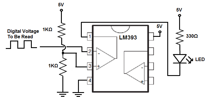
So in this circuit, as all chips require, we give power to the chip. We give 5V to pin 8 and we ground pin 4. This gives the chip power.
The op amp has 2 input terminals, the inverting terminal and the noninverting terminal.
To the noninverting terminal, we connect a reference voltage. A very popularly used technique when using a voltage comparator to measure digital voltage in this case is to take 2 resistors of the same value, put them in series, and then connect the midpoint of these 2 resistors to the noninverting terminal. This makes the voltage at the noninverting terminal half of the supply voltage. In this case, using 5V as the supply voltage, dividing this voltage in half is 2.5V. So this is what we feed into the noninverting terminal.
Then we feed the digital signal we want to read to the noninverting terminal. If the voltage at the inverting terminal is greater than at the noninverting terminal, the output goes low and turns on. So, in this case, if the voltage at the inverting terminal is greater than 2.5V, then the output turns on. If the voltage is less than 2.5V, the output is HIGH and the output device is off, in this case an LED.
So the voltage comparator is one very effective way of reading a digital voltage.
Reading a Digital Voltage with a Logic Chip
Another way to read a digital voltage signal is using a logic chip.
Though many different types of logic chips can be used, a NAND gate is a very popular logic chip because it can be converted into any type of logic chip. It's a universal logic chip, meaning it can be wired to be any type of other logic chip, such as an inverter, AND gate, OR gate, etc.
So a logic chip, such as a NAND gate, can be used to read a digital voltage signal.
Based on whatever logic chip you are using, whether a NAND gate, AND gate, OR gate, etc determines what the output will be for a given input.
Based on the logic of the logic chip being used determines the output.
In this case, I'm going to use a NAND gate logic chip.
A NAND gate logic chip is ON only if both inputs are LOW. And it is oFF only if both inputs are HIGH.
If you're measuring a single digital voltage signal, then you can just tie the 2 inputs together of the NAND gate. This way, the inputs are either both ON or both OFF. This will be explained more below. But just think of this, if you tie both inputs together of a NAND gate, both inputs have to be the same (since they're tied together). This means you can only have 2 HIGHs as the inputs or 2 LOWs as the inputs. If 2 HIGHs, the output is LOW. If 2 LOW inputs, the output is HIGH.
Knowing this fact, you can tell whether the input is HIGH or LOW, based on the state of the output.
So below is a circuit using the popular 4011 NAND gate chip to read a digital voltage signal.
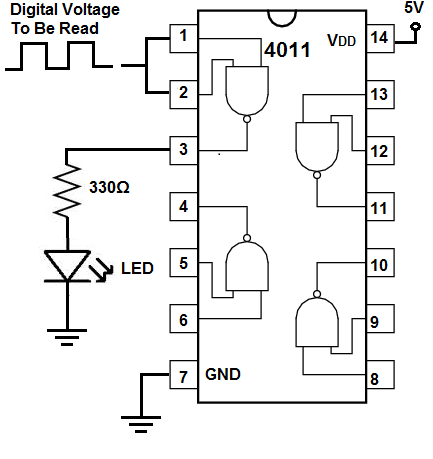
So we have the 4011 NAND gate chip. We connect power to it, 5V at pin 14 and we ground pin 7.
Since this chip is a NAND gate chip, it works according to NAND gate logic.
A logic chip measures voltage pretty much at the halfway point of the supply voltage. In this case, we're giving the chip 5V of supply voltage. So if the signal going into the input of the logic chip is below 2.5V, the chip interprets the signal as a LOW signal. If the signal going into the input is above 2.5V, the chip interprets the signal as a HIGH signal.
Again, according to NAND gate logic, 2 HIGHs makes a LOW output. 2 LOW inputs makes a HIGH output. So we're able to read whether the digital signal is HIGH or LOW based on the output of the NAND chip.
So now, unlike with the voltage comparator circuit previously, the output will be HIGH when the input is LOW. Based on the logic gate you use, you can make any situation. If you want the output to be HIGH when the input is HIGH, then you would an AND gate or convert a NAND gate into an AND gate. You can do anything based on these chips.
So a logic chip is another way to read a digital voltage signal.
Reading a Digital Voltage with a Microcontroller
Another way to read a digital voltage signal is through a microcontroller such as an arduino microcontroller.
An arduino microcontroller is equipped to be able to read or write HIGH or LOW digital signals.
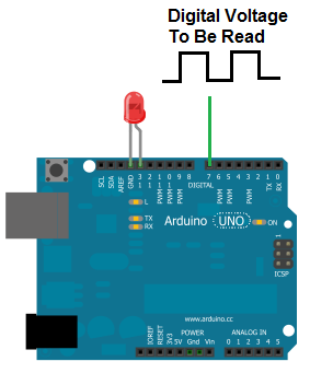
So if you connect up the microcontroller so that is has power and all functionality and you connect the digital signal you want to read to one of the digital terminals (it will work too connected to an analog terminal) and write up the necessary code, you can easily read a digital voltage signal through a microcontroller.
Most microcontrollers such as the arduino have analog-to-digital converter chips which are capable of reading analog or digital voltages.
The downside to using a microcontroller to read a digital voltage is that it requires both hardware and software programming in order to work. Using a voltage comparator
or logic chip is purely done on hardware. If using software in addition is no problem, then a microcontroller is a very easy way to do it.
So these are probably the most common and easiest way to read in circuitry whether a digital signal is HIGH or LOW.
This is important for many types of devices which output a digital voltage. To be able to read this digital voltage, you going to need
some type of chip whether it's a voltage comparator, a logic chip, or a analog-to-digital converter (a ADC can read digital or analog voltage).
Related Resources
What is an Ideal Voltage Source?
What is a Constant Voltage Source?
What is Open Circuit Voltage?
RMS Voltage and Current- Explained
What is Peak Voltage?
What is Peak-to-Peak Voltage (VPP)?