
How to Read Analog Input in a PIC Microcontroller in C
In this article, we show how to read analog input in a PIC microcontroller in the C programming language.
So working with analog signals is very important for many circuit applications.
Many different types of components are analog, including temperature sensors and pressure sensors.
Analog signals can signals that can take up ideally an infinite number of values between the low and high voltage of a microcontroller system (ex: 0v-5v).
Analog signals are not like digital signals that can only be on or off; they can take a wide range of values between 0 and the maximum voltage of the system. Thus, they can confer intensity, not simply the on-off status of a device.
PIC microcontrollers come with an analog-to-digital converter (ADC).
The ADC takes in an analog signal such as from a sensors and converts into a digital value in binary form. We can then take this binary number and convert to something we as humans more understand, which is normally a digital value. Thus, we can get a reading from a temperature sensor and output a digital value, such as 75 degrees Fahrenheit.
So we have to know how to work with the ADC.
Before we go into the registers that control the ADC, realize that though in theory the ADC can take on infinite values between 0V and 5V, in reality it doesn't. The ADC is limited by its resolution. Thus, it still has discrete increments.
The PIC18F4525 will is a 10-bit ADC. Thus, it has a range of 1024 values (210).
Since the maximum voltage of the microcontroller is 5V, the ADC has discrete incremental values of 4.88mV (5V/1024V= 0.00488 V or 4.88mV). So it can't detect voltage less than a few millivolts of difference but anything over 4.88mV will be classified as a different value.
In order to use the ADC, there are 3 control registers we need to work with: ADCON0, ADCON1, and ADCON2.
The ADCON0 register allows the programmer to turn on the ADC and select which analog input, or channel, is connected to the ADC.
The datasheet for the ADCON0 register is shown below.
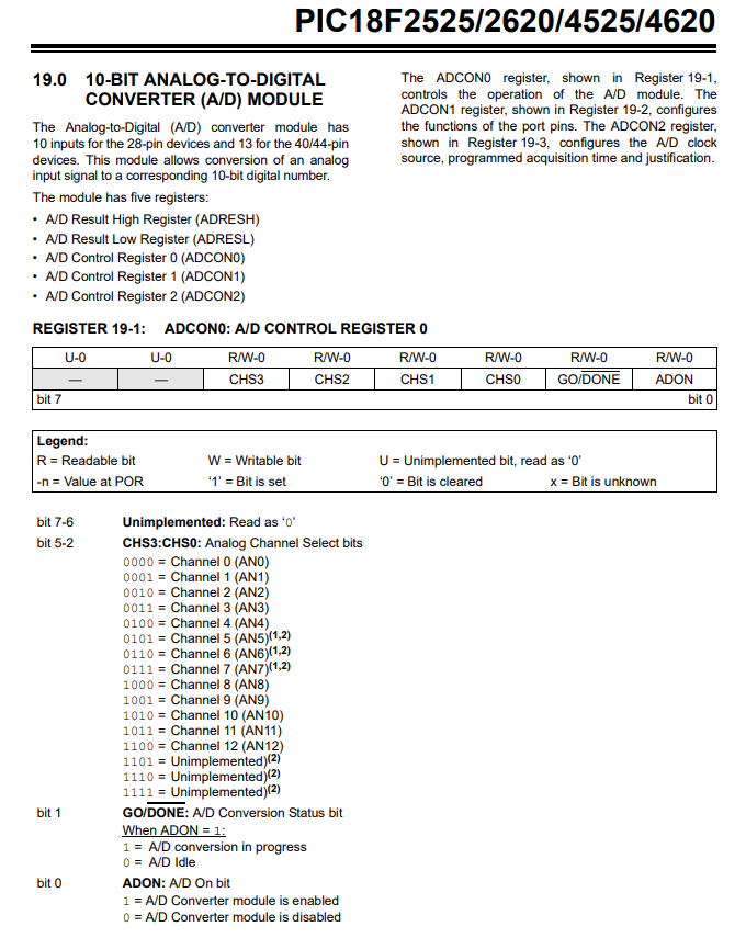
Bit 7 and 6 are not used on this register and are read as 0.
Bits 5-2 determine which channel of the ADC is selected. The PIC18F4525 microcontroller has 13 channels, channels 0-12. The bits used determine which channel is selected.
Bit 1, GO/Done. This bit needs to be set to 1 in order to start the ADC conversion and it tells the programmer when the conversion is finished or done by changing the bit to 0. The microcontroller does this automatically as a signal that the ADC conversion has been completed.
Bit 0, ADON, allows us to turn on or off the ADC. A logic '1' turns on the ADC. A logic '0' turns it off.
Next, the ADCON1 register controls whether the 13 inputs are to be used as analog or digital.
The datasheet for the ADCON1 register is shown below.
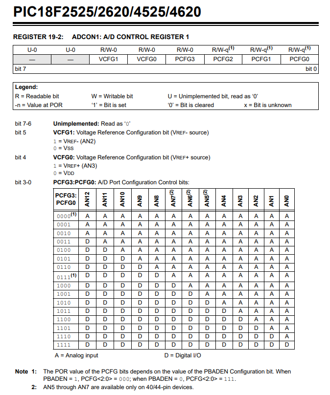
Bits 7 and 6 are not used and are read as 0.
Bit 5 is the negative reference voltage for the level of the analog input. The default, or normal setting, is to use the supply to the PIC, that is, VSS or ground.
Bit 4 is the positive reference voltage for the level of the analog input. The default, or normal setting, is to use the suply to the PIC, that is VCC or VDD.
Bits 3 to 0 control which pins are analog and which are digital.
The datasheet for the ADCON2 register is shown below.
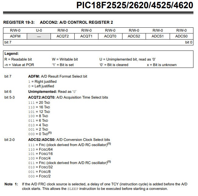
The ADCON2 control register is used to first decide what format the result of the ADC is stored in.
Let's start with the most significant bit, bit 7. Bit 7 is the ADFM bit, which stands for A/D Result Format Select Bit. This bit determines whether the result of the ADC conversion is left justified or right justified.
Let's now explain this because you won't know what this means.
After the microcontroller does the ADC conversion, the ADC returns a 10-bit binary number as the result.
Remember, though, that the PIC18F4525 microcontroller is an 8-bit microcontroller, where registers are 8 bits in size.
This means that 2 registers are required to store the result of the 10-bit binary result.
The 2 registers that store the result of the ADC conversion result is ADRESH and ADRESL.
If we right justify the result, 8 bits are stored in the ADRESL register and 2 bits are stored in the ADRESH register (b1 b0).
If we left justify the result, 8 bits are stored in the ADRESH register and 2 bits are stored in the ADRESL register (b7 b6).
In our example, we will left justify the result, so 8 bits will be stored in the ADRESH register and 2 bits in the ADRESL register (b7 b6).
Bit 6 is not used. Thus, it is '0'.
Bits 5-3 selected the TAD, which is the period of the timing waveform controlling the ADC conversion process.
Choosing this value requires some background knowledge, which we will now delve into.
So in order to understand what TAD option to select, you need to appreciate what happens when you turn the ADC on and start the ADC conversion process.
When you work to an ADC conversion, the PIC will connect the ADC to the particular input, or ADDC channel, that is measuring the phyiscla analog input. Once the ADC is connected to the input, it will use the voltage at that input to charge up a capacitor in what is termed a sample and hold circuit. In order for the capacitor to fully charge to this voltage, it will take a certain amount of time. This charge up time depends on a number of factors including the size of the capacitor and the impedance in series with the capacitor. For the PIC18F4525 microcontroller, this capacitor, CHOLD, is 25pF. Using the formula to calculate the minimum acquisition time, we obtain a value of 2.4μs (microseconds). This is the minimum time it takes for the capacitor to chage up fully before the ADC conversion is started. Thus, when we are selecting a TAD time, it must be greater than this value before we start the ADC conversion. This is all outlined in the PIC18F4525 datasheet in section 19.1.
So, again, for the PIC18F4525 datasheet, we must get the PIC microcontroller to wait 2.4μs before the ADC starts the conversion process; if it doesn't wait this necessary time, the conversion can be inaccurate.
There are 2 ways you can go about creating this delay.
One way is you can do it manually creating a delay routine that waits this specified time before starting the conversion process. If you use this method, bits 5,4, and 3 of the ADCON2 register must bet set to a logic '0'. To start the conversion process, you simply have to set bit 1 of the ADCON0 register to a logic '1'.
The second way is creating the delay through setting bits in the ADCON2 register, which specifically are bits 5 to 3.
To be able to use this method correctly, you have to know the period 'T' of the frequency of the timing waveform controlling the ADC conversion process. Microchip terms this period "TAD".
This leads to the next thing. We have to select our timing waveform. These are bits 2,1, and 0. This is decided by the oscillator we are using for our system clock. Remember that we are using a 8MHz oscillator. We decide to divide this 8MHz signal by 8, which gives us 1MHz. The period of a signal is, T= 1/f, which would be 1μs. So 1μS would be our TAD.
Remember that we need to create a delay of at least 2.4μs.
Going back to the datasheet, we have the option to select 0TAD, 2TAD, 4TAD, 6TAD, 8TAD, 12TAD, 16TAD, and 20TAD.
0 or 2 TAD would not be enough.
We must select 4TAD, which will give us a delay of 4μs.
We don't want to select anything greater than this because the delay will be too long, creating unnecessary time waste.
Therefore, we set the bits 5,4,and 3 to "010".
So going through all the bits of the ADCON2 register, we set the bits to "00010001".
Below is the code of the full program that reads the analog voltage from channel 0, AN0, of the PIC microcontroller and writes it to PORTB and PORTC, which have LEDs attached to them.
You would need LEDs attached to all pins of PORTB and then to pins RC7 and RC6 of PORTC. This will represent the full 10 bits of the result of the ADC output.
So we, of course, have to put everything in our main() function, which is where the program starts.
The first thing we do is clear out PORTA, PORTB, and PORTC, to make sure that nothing is turned on connected to them when the program starts. We want to start with no outputs on.
We are only using one bit of PORTA, RA0, as an input, so we set TRISA to a value of, 0x01
We set all bits of PORTB and PORTC as outputs, since we connect LEDs to these pins.
We set the oscillator to 8MHz.
We then turn on the ADC and select channel 0 (AN0).
We then make all bits digital in PORTs A, B, C, and D except bit RA0, which will be analog.
We then create the necessary delay so that the ADC process can be converted accurately.
We then have a while loop that acts as infinite loop.
We start the ADC conversion and do nothing until this conversion has completed.
Once the conversion is completed, we write the contents of ADRESH to PORTB and ARESL to PORTC.
This gives us the full 10 bits of the ADC result output to LEDs, so that we can visually see the output.
This is a basic circuit.
What you probably want is to take this ADC result and display the result in decimal in a numerical format that
makes sense to us, humans, like the temperature in Fahrenheit or celsius or the speed of an object in miles per hour
or rotations per minute. We can connect an LCD to our PIC microcontroller so it can show us this human readable result
once we provide the necessary formulas to our program to get this output.
And this is how we can read analog input in a PIC microcontroller in
C.
Related Resources
How to Set the Ports of a PIC Microcontroller in C