
How to Read Input from an I/O Pin on a STM32F407G Discovery Board in C

In this article, we go over how to read input from an I/O pin on a STM32F407G discovery board in C.
The STM32F407G discovery board comes with a STM32F407VGT6 microcontroller featuring 32-bit ARM® Cortex®-M4 with FPU core, 1-Mbyte Flash memory, 192-Kbyte RAM in an LQFP100 package.
The STM32F407G is a great board to use to do embedded programming because it comes with all the hardware needed to execute code on the board, including an ST-LINK/V2-A embedded debug tool. Therefore, with this board, no external debugging tools are necessary; everything is already on the board.
Doing anything in embedded programming is involved because it requires a lot of datasheet reading and understanding. Reading the input or voltage of an I/O pin is no different. It takes a number of steps.
So we will write a program that makes pin 0 of GPIOA an input. We then read the input voltage of this pin. If the input is 1 or connected to VDD, we turn an LED connected to GPIOD pin 0. If the input is 0 or connected to GND, we turn off the LED connected to GPIO pin 0.
You must know how to identify the GPIO port pin which the LED will be connected to.
A number of concepts must be understood in order to do this program.
Then you must activate the GPIO peripheral, which is done by enabling its clock. Until you enable the clock of a peripheral, the peripheral is dead and neither functions nor takes any configuration values set by you. Only once you activate the clock for a peripheral are you then able to set configuration values and give control-related commands or arguments.
Then you must configure the GPIO pin mode as output for the LED and as input for GPIOA pin 0. A GPIO pin, which is a general-purpose pin can function as input or output. Since we are looking to read GPIOA pin 0, we set it as input. Since we are looking to turn on an LED, in this case, our it must be set as output.
We then have an if statement. If the input read from GPIOA pin 0 is LOW, then we write a 0 to the pin connected to the LED, turning it off. If the input read from GPIO pin 0 is HIGH, then we write a 1 to the pin connected to the LED, turning it on.
So let's show the code how to turn on each of these LEDs.
We now will explain the code.
Within our main function, we declare 3 32-bit variables.
These variables are crucial and form the foundation for our code.
So the first variable is for the clock control register, so that we can enable the peripheral clock register.
The RCC, the Reset and Clock Control, for the board handles clock control.
According to the memory map, the base address for the RCC is, 0x4002 3800
So RCC forms the basis for all clock control and above is the base address for RCC.
What we want to do is enable the peripheral clock register, specifically for GPIO.
The following image below helps us to navigate this.
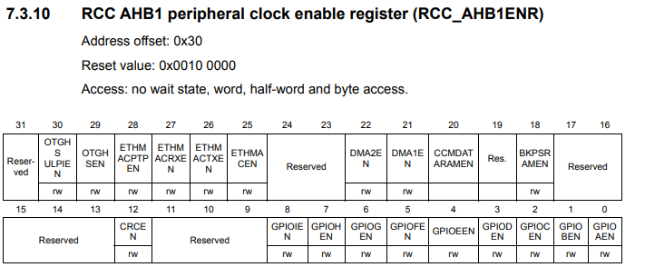
Looking at the RCC AHB1 peripheral clock register, we see that this register has an address offset of 0x30. What this means is that we have to add the base address of RCC to this address offset of 0x30. This gives us a result of, 0x4002 3800 + 0x30, is 0x4002 3830.
This address gives us the address for the RCC AHB1 peripheral clock register, which is the register that allows us to work with the GPIOA and GPIOD ports.
The only other thing we must do is set the clock register specifically to work with ports GPIOA and GPIOD. To do this, we must set bit 0 (1st bit) of the RCC AHB1 peripheral clock to a HIGH value to work with GPIOA. We set bit 3 (4th bit) of the RCC AHB1 peripheral clock register to a HIGH value to work with GPIOD.
We do this in the line, *pClkCtrlReg |= (1 << 3);
This sets bit 3 to HIGH, which enables the peripheral clock register for the GPIOD port.
The line, *pClkCtrlReg |= (1 << 0);, sets bit 0 to a HIGH, which enables the peripheral clock register for the GPIOA port.
Next, we need to configure the GPIO port mode register.
The diagram below helps us to navigate this.
This is where we can configure pins of the port as input or output.
The base address for the GPIOD port is, 0x4002 0C00
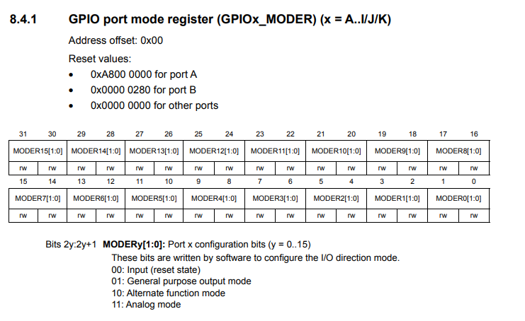
The GPIO port mode register has an address offset of 0x00.
In order to turn on pin 12, we see that this register is a 32-bit register, and bits 24 and 25 correspond to bit 12 of the GPIO port.
As can be see in the MODE configuration bits, 00 makes the pin an input, 01 makes the pin an output, 10 gives an alternate function mode, and 11 makes the pin analog.
In this case, since we want to turn on an LED, we want to make pin 12 an output, so we want to set the bits 24 and 25 to 01.
This is done in the line, *pPortDModeReg |= (1 << 24);
Now to configure the PORTA pin 0 as input, we first need to look up that the base address of PORTA is, 0x40020000
This is shown in our code in the line, uint32_t *pPortAModeReg= (uint32_t*)0x40020000;
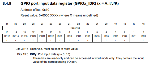
If looking up the GPIO port input data register, which enables a PORT to function as input, we see that it has an address offset of 0x10. We add this offset to the base address of the GPIOA register to get an address of 0x40020010;
This is shown in our code in the line, uint32_t *pPortAInReg= (uint32_t*)0x40020010;
This is shown in the diagram below.
Next, we must configure pin 0 as input, which we do through the line, *pPortAModeReg &= ~(3 << 0);
Pin 0 comprises bits 0 and 1 of the GPIO Port Mode Register. To make a pin an input, we set the pin to a value of 00.
3 really is 11 in binary. The negation, ~, makes it a 00 that we write to bits 0 and 1.
We then create a while loop that loops forever. This is important because we always constantly want to be assessing the value of the input being read at GPIOA pin 0.
We create an 8-bit variable, pinStatus, which allows us to read the input logic state at GPIOA pin 0.
Realize that this is an 8-bit variable and we only want to read 1 bit, bit 0. Therefore we AND the result with 0x1, which is a binary 1. This is the same as 00000001. This zeroes out all the bits other than bit 0.
We then have an if statement. If input read is a logic HIGH, then we turn the LED on using the line, *pPortDOutReg |= (1 << 12);
If the input read is a logic LOW, then we turn off the LED using the line, *pPortDOutReg &= ~(1 << 12);
And this is how to read the input state of an I/O pin with a STM32F407G discovery board
in C.
Related Resources
How to Set Bits of a Number in C
How to Clear Bits of a Number in C