
How to Select Alternate Functionality for a GPIO Pin with an STM32F407G Discovery Board in C

In this article, we go over how to select alternate functionality for a general-purpose I/O (GPIO) pin when working with an STM32F4xx discovery board in C.
General purpose I/O pins, as the name suggests, are pins which normally are used for any general-purpose input or output use. This could include using any pin as an input for a switch or using a pin as as an output for an LED.
General purpose I/O pins, however, do not function only as I/O pins but can also serve alternate functions, such as a timer pin or a clock output pin or an SPI pin or a USART pin, etc.
When a GPIO pin is used for any alternate purpose other than as a general purpose input or output pin, then it is said to be in alternate function mode.
We will show in this article how to select alternate functionality for a GPIO pin with an STM32F407G discovery board.
Each pin of a GPIO PORT has up to 16 different alternate functions.
The datasheet for a microcontroller should have what is referred to as 'Alternate Function Mapping' for each GPIO port of a micontroller. This will tell what alternate function each pin can have in a given GPIO Port.
The datasheet for the STM32F407G discovery board is shown at the following link: STM32F407G Datasheet.
Let's look at an example of this.
So let's at the alternate function mapping of GPIO PORTA of the STM32F407G discovery board.
Below is the alternate function mapping for GPIO PORTA.
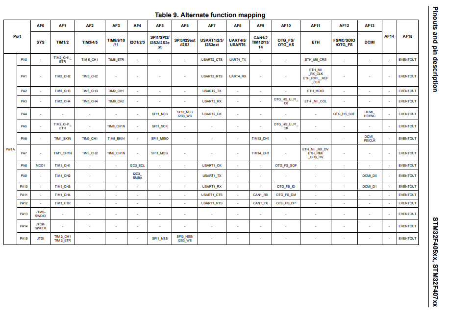
So looking at this datasheet, we can see that each pin can have up to 16 different alternate functions. These alternate functions are shown from AF0 (alternate function 0) to AF15 (alternate function 15).
So, as an example, let's look at pin 8. Again, this port A. So this is PA8.
You can see for pin, PA8, set in AF0 mode functions as an MCO pin. This is is a microcontroller clock output pin, which a clock signal can be output, which can then be read by an oscilloscope or logic analzyer.
The same pin, PA8, set in AF1 mode, functions as TIM1_CH1, or channel 1 of timer 1.
You can see that PA8 has no alternate functions when set to AF2 or AF3 modes; thus, they function as general purpose I/O pins if placed in these modes.
When set to AF4 mode, pin PA8 function as I2C3_SCL.
When set to AF5 and AF6 modes, pin PA8 has no alternate functions and simply function as general purpose I/O pins.
When set to AF7 mode, pin PA8 function as USART1_CK.
There are no alternate functions when set to AF8, AF9, AF11, AF12, AF13, or AF14.
When set to AF10, the pin function as OT_FS_SOF.
In our program, we will write a program to make set pin 8 of GPIO Port A to AF0, making it function as MCO1, which is a microcontroller clock output pin.
In case you're wondering how you set a pin in a certain alternate function mode, the first thing you have to do is set the pin in alternate function mode through the GPIO port mode register.
This is shown below.
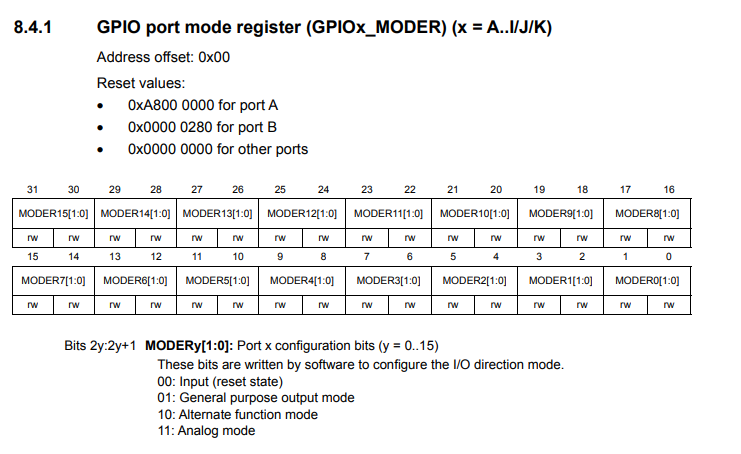
To set a pin in alternate function mode, 10 must be set to the pin.
After the pin is in alternate function mode, you then set the pin to the specific alternate function mode (AF0, AF1, AF2 ...) through either the alternate function low register or the alternate function high register.
The alternate function low register is for pins 0-7 of a certain given port.
The alternate function high registe ris for pin 8-15 of a certain given port.
So both of these registers are used when you are setting the mode for a GPIO pin in alternate function mode to determine exactly what alternate function the GPIO pin will have.
Before we go more into this, know that each GPIO PORT has 16 pins that go from pin 0 to pin 15. This is important to know when dealing with the alternate function low register and the alternate function high register.
This is because the alternate function low register is when you are dealing with the GPIO pins 0 to 7 of a given port.
The alternate function high register is when you are dealing with the GPIO pins 8 to 15 of a given port.
So if you are dealing with pins 0 to 7 of a GPIO port, you set the function for that pin with the alternate function low register.
If you are dealing with pins 8 to 15 of a GPIO port, you set the function for that pin with the alternate function high register.
To examine this with more depth, let's look at the diagrams for both of these registers.
Below is the diagram for the GPIO alternate function low register.
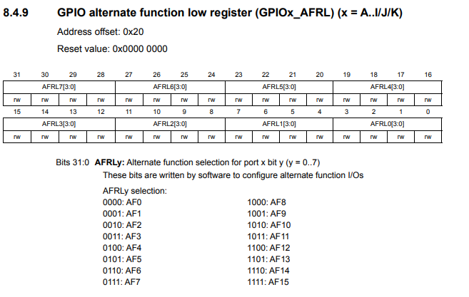
As all registers with the STM32 microcontrollers, each of these registers are 32 bits.
You can see that pins 0 to 7 are referenced and each pin is allocated 4 bits.
The reason each pin is allocated to 4 bits is because there are 16 possible alternate functions for each pins (even though this bits are simply reserved). So each of the pins can be placed in any 1 of 16 modes to determine what alternate function a pin will have. Since each pin is allocated to 4 bits to address the 16 possible alternate functions and there are 32 bits, then the register can only address 8 pins (0 to 7).
Therefore, it was decided by the manufacturer to have an alternate function low register (for pins 0 to 7) and an alternate function high register (pins 8 to 15).
Let's now look at the diagram for the GPIO alternate function high register.
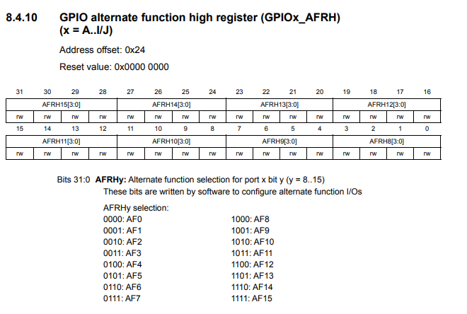
You can see that that the high register references pins 8 to 15. It's exactly the same in which 4 bits are allocated to each pin to address 16 possible alternate functions for each pin.
In this case, since we are working with pin 8 of GPIO Port A, we set the alternate function mode in the alternate function high
register.
So now let's go to our code which selects the alternate functionality of AFO to pin 8 of GPIO Port A, which makes it acts as
MCO1.
So we have a full complete program here which gives alternate functionality to GPIO port A pin 8, making it function as MCO1, which is a microcontroller clock output, in this case, outputting a 16MHz HSI clock signal.
Remember when you're dealing with any GPIO port, you have to turn on the peripheral clock for that port.
Then we configure PA8 to be in alternate function mode, which is done through the GPIO port mode register. Alternate function mode is given by setting 10 to the pin.
Since pin 8 is in the alternate function high register, we reference the alternate function high register. Since MCO is AF0 mode
and pin 8 is the first pin in the alternative function high register, we clear the 4 bits of the register (to 0000). This makes pin 8 be in
AF0 mode, enabling it to function as MC01.
And this is how we can select alternate functionality for a GPIO pin with an STM32F407G discovery board in C.
Related Resources
How to Set Bits of a Number in C
How to Clear Bits of a Number in C