
How to Select Individual Bits of a PIC Microcontroller in C
In this article, we show how to select individual bits of a PIC microcontroller in the C programming language.
So PIC microcontrollers have PORTs and each PORT is composed of pins, or bits, which can be used in a circuit as input or output.
We can work with each PORT as a whole which is made up of several bits. In an 8-bit microcontroller, each PORT is composed of 8 bits. Or we can work with each bit individually, where we specifically address a specific bit in the microcontroller.
So, each PIC microcontroller has PORTs, which are registers composed of bits. If the microcontroller is an 8-bit microcontroller, these PORTs will be composed of 8 bits each.
With the PIC18F4525 microcontroller, each PORT is 8 bits, as it is an 8-bit microcontroller. This microcontroller has 4 PORTs: PORTA, PORTB, PORTC, and PORTD.
Just to give you a visual perspective of this, the schematic pinout of the PIC18F4525 microcontroller is shown below.
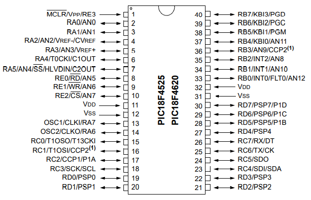
You can see based on this pinout diagram that this microcontroller has 4 PORTs: PORTA, PORTB, PORTC, and PORTD.
As the PIC18F4525 microcontroller is an 8-bit microcontroller, each PORT has 8 bits.
PORTA has the following 7 bits from least significance to greatest signficance: RA0, RA1, RA2, RA3, RA4, RA5, RA6, and RA7.
PORTB has the following bits: RB0, RB1, RB2, RB3, RB4, RB5, RB6, and RB7.
PORTC has the following bits: RC0, RC1, RC2, RC3, RC4, RC5, RC6, and RC7.
PORTD has the following bits: RD0, RD1, RD2, RD3, RD4, RD5, RD6, and RD7.
This is important because we use these notations in order to be able to address a bit specifically.
So in our program below, we make all pins of all PORTs outputs, we set each pin as digital, and then we turn on the output of each pin by individually specifying each pin.
After that, you must decide whether the pins should be analog or digital.
Analog can take on a range of "infinite" values between 0 and the maximum voltage that the pin accepts (such as 3.3V or 5V).
Digital only can take on 2 values, either 0V or 3.3V or 5V, or Off or On.
Analog is used for analog devices such as microphones, speakers, temperature sensors, pressure sensors, etc.
Digital is used for digital devices such as a simple switch, a digital light source, or a digital chip.
As stated before, we can to explicitly define a pin as analog or digital.
By default, all pins are analog.
Thus, to make the pins digital, we have to explicitly define them as digital.
So we show how to do this below.
First, we set PORTA and PORTB as outputs.
We then turn off the ADC through the ADCON0 register and set all the PORTs as digital through the ADCON1 register.
What we then want to do is turn each individual bit on. So far, we have just declared all bits to be outputs and set each bit to digital. Now in order to turn each bit on individually, we reference each bit and each it a value of logic '1', which turns the output on. A logic '1' is on, while a logic '0' is off.
In this example, we set every bit in PORTs A, B, C, and D to a logic value of '1', turning on each of these outputs.
So, for example, if you had LEDs connected to each of these pins, they would all turn on with the following code above.
If we wanted to turn off all of the outputs, then we would have the following code below.
Now all the outputs are turned off at each of the individual bits of all PORTs.
Thus, in the case of LEDs, all the LEDs would be turned off.
And this is how to select individual bits of a PIC microcontroller in
C.
Related Resources
How to Set the Ports of a PIC Microcontroller in C