
How to Set up the External Oscillator (HSE) Clock in an STM32F407G Microcontroller Board in C

In this article, we show how to set up the external oscillator (HSE) clock in an STM32F407G microcontroller discovery board, so that the HSE clock can function as the system clock.
By default, the HSI, or high-speed internal, clock is the clock used as the system clock. However, we can change this to either the HSE clock or the PLL clock.
In comparison to the HSI clock, the HSE clock offers an advantage in that it is more accurate than the HSI clock, which relies on RC circuitry to generate the clock signal.
With the STM32F407G discovery board, it comes with an 8MHz crystal oscillator already connected to the board. So we don't have to connect a crystal oscillator; we simply can use the one provided with the board. This saves us from having to connect external components.
In order to set up the external oscillator (HSE) clock, we need to do a few configuration changes in some registers.
We need to enable the HSE clock by setting HIGH the HSEON bit in the RCC Clock Control Register (RCC_CR). By default, the HSE clock isn't even enabled until we intentionally enable it. The HSI clock is enabled by default, so it would not need any configuration.
After this, we must wait until the HSE clock from the external crystal oscillator stabilizes. The oscillator must produce stable output before it can be used. This is one advantage of the HSI signal in that it has less startup time. The external crystal oscillator takes more time to startup.
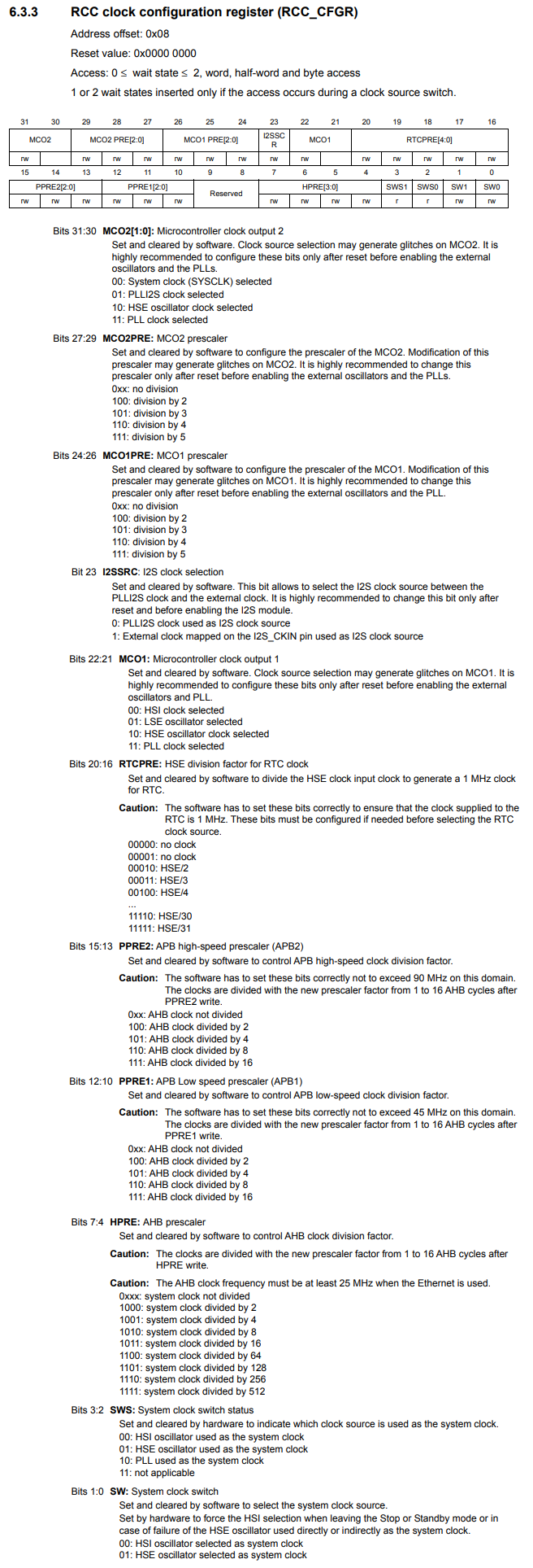
Then after this, you just have to set the HSE clock as the system clock for the microcontroller in the RCC Clock Configuration Register (RCC_CFGR).
So let's see how all of this works in the C code below.
So let's now go over this code.
So since we're dealing with clocks, the base register is the the beginning of RCC, which is 0x40023800UL
Next, we need to be able to reference the RCC_CR register.This has an address offset of 0x00
We then create a pointer variable, which points to this address.
We then deference this variable and set bit 16 to 1. This turns on the HSEON bit, which enables the HSE clock. Without turning on this bit, the HSE clock is disabled and cannot be used at all. So this is the starting point for operating the HSE clock.
The RCC Clock Control Register (RCC_CR) is shown below.
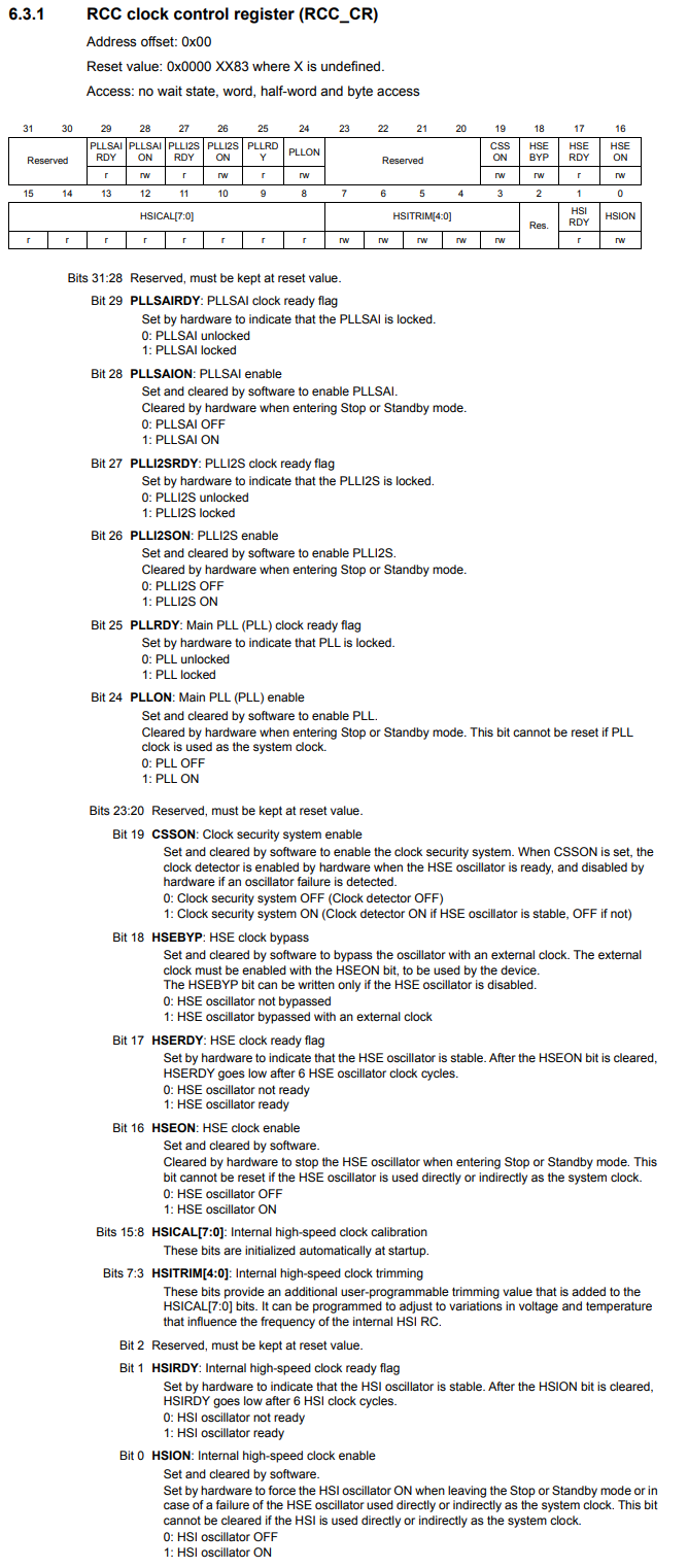
Another important aspect of this register is bit 17, the HSERDY bit, which is the HSE clock ready flag.
According to the datasheet, when this bit is 0, the HSE oscillator is not ready. When this bit is 1, the HSE oscillator is ready.
So we must check this bit to see when it turns to 1. When it does, this means that the crystal oscillator has stabilized and can now be used as the system clock.
This is why we have a while statement, while(!(*pRccCrReg & (1 << 17)));
When bit 17 is 0, this means the HSE oscillator is not ready. This produces a while(1), which loops infinitely.
When bit 17 is 1, this means that the HSE oscillator is ready. This produces a while(0), which exits out of the loop.
Next, we create a pointer variable for the RCC_CFGR register.
Within this register, we have select the HSE oscillator as the system clock.
We do this through the SW, system clock switch, bits 1:0
We do this through by setting the SW bits to 01.
So we have to set bit 0 of the RCC_CFGR to 1.
The RCC_CFGR register is shown below.
Now everything is set and the system clock is now an external oscillator HSE signal.
The STM32F407G board has an on-board 8MHz crystal oscillator.
If you were to measure this signal, you should see that it has an 8MHz frequency signal.
This is exactly what we do in the next code.
In order to measure the signal, we output the signal to the MCO1 pin. From there, we can measure the output signal with either an oscilloscope or a logic analyzer.
In order to do this, we must set up alternate functionality mode for pin PA8 to function as an MCO pin.
This is shown in the code below.
With this code now shown above, you should be able to measure the output HSE clock
signal from the microcontroller's PA8 pin, which now is functioning as an MCO pin (microcontroller
clock output pin).
So this is how to set up the external oscillator HSE clock
in an STM32F407G microcontroller board.
Related Resources