
How to Set up an Oscillator for a PIC Microcontroller in C
In this article, we show how to set up an oscillator for a PIC microcontroller in the C programming language.
An oscillator is a necessary component for a microcontroller circuit, because the oscillator function as the clock source.
A microcontroller program needs a clock in order to synchronize instructions. Without a clock, everything would be random. A clock is needed so that instructions are carried out synchronized and, thus, it can all work.
There are several types of oscillators that can be set up to work PIC microcontrollers.
An external oscillator can be used in which you set up an RC circuit or you input a crystal oscillator of some frequency.
But an external oscillator does not have to be used. The PIC microcontroller comes with an internal oscillator block. This can eliminate the need for external oscillator circuits on the OSC1 and/or OSC2 pins.
So we will configure the internal oscillator block of the PIC microcontroller to output an 8MHz signal, which will be used for our microcontroller clock source.
So in order to configure this internal oscillator block to function as our system clock, we need to ser teh bits in the OSCillator CONtrol register, OSCCON. This allows us to customize the signal sent out by the internal oscillator block.
Several things can be customized, including the output frequency signal, where 8 possible oscillator frequencies can be selected, including 8MHz, 4MHz, 2MHz, 1MHz, 500KHz, 250KHz, 125KHz, and 31KHz. Besides the frequency selected, you can choose whether you want the frequency to be stable or not.
The Oscillator Control Register for the PIC18F4525 microcontroller is an 8-bit register .
Thus, we have to set the 8 bits to get the customized output signal.
The map for the bits of the oscillator control register is shown below.
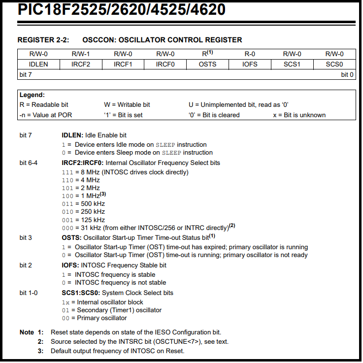
Starting from the most significant bit, bit 7u, we have the IDLEN bit, which is used for the sleep mode. We do not utilize idle mode now, so we set this bit to '0'.
The next 3 most significant bits, bit 6 to bit 4, is IRCF2,IRCF1,and IRCF0. These bits select the frequency of the signal. A selection of 111 is an oscillator frequency of 8MHz. 110 is 4MHz. 101 is 2MHz. 100 is 1MHz. 011 is 500KHz. 010 is 250KHz. 001 is 125KHz. 000 is 31KHz.
Bit 3 is the oscillator start-up timer (OST) time-out status bit. This we set to 0.
Bit 2 is the INTOSC frequency stable bit. In order to make the signal stable, we give this bit a '1'.
Bit 1 and Bit 0 are the System Clock Select bit. '00' allows us to select the primary oscillator as the system clock.
Thus, the code to use the internal oscillator block as the primary oscillator source
to output a stable 8MHz clock signal is shown below.
Remember that we need configuration statements in order to choose the internal oscillator block as our primary oscillator source, which is INTIO67.
Once this is set up, then we can use OSCCON to select our customized signal, which is a stable 8MHz signal.
Again, you can change this to any frequency by modifiying bits 6 to 4. You can also
modify other advanced features such as the sleep mode.
And this is how to set up the oscillator for a PIC microcontroller in
C.
Related Resources
How to Set the Ports of a PIC Microcontroller in C