
How to Toggle an LED with a Timer in Output Compare Mode in an STM32F446 Microcontroller Board in C
In this article, we show how to toggle an LED with a timer in output compare mode in an STM32F446 microcontroller board in C.
So, in this project, we are going to use a general-purpose timer, specifically timer 2 (TIM2).
We are going to set this general-purpose timer to be in output compare mode.
What output compare mode does is it creates a waveform at the output, such as pulse lasting for a certain duration that you set. The mode that we can select can include toggle mode or it can be PWM mode, amongst others.
In this project, we will set the output compare 1 mode to toggle, because we want to toggle an LED.
If you were doing a project such as driving a motor, we may use PWM mode.
But the basic principle is it causes an output waveform from the timer that we can then force onto a GPIO pin to power on a load.
So a general-purpose timer in STM32 boards have various channels as outputs.
The timer we are working with in this case is timer 2. It has 4 output channels.
So this means is that we can generate a waveform from timer 2 and this waveform can then be output to any of the various channels of this timer.
In case, you are wondering which pins are the channels for timer 2, you can find this in the Alternate Function Mapping of GPIO Port A.
This is shown below.
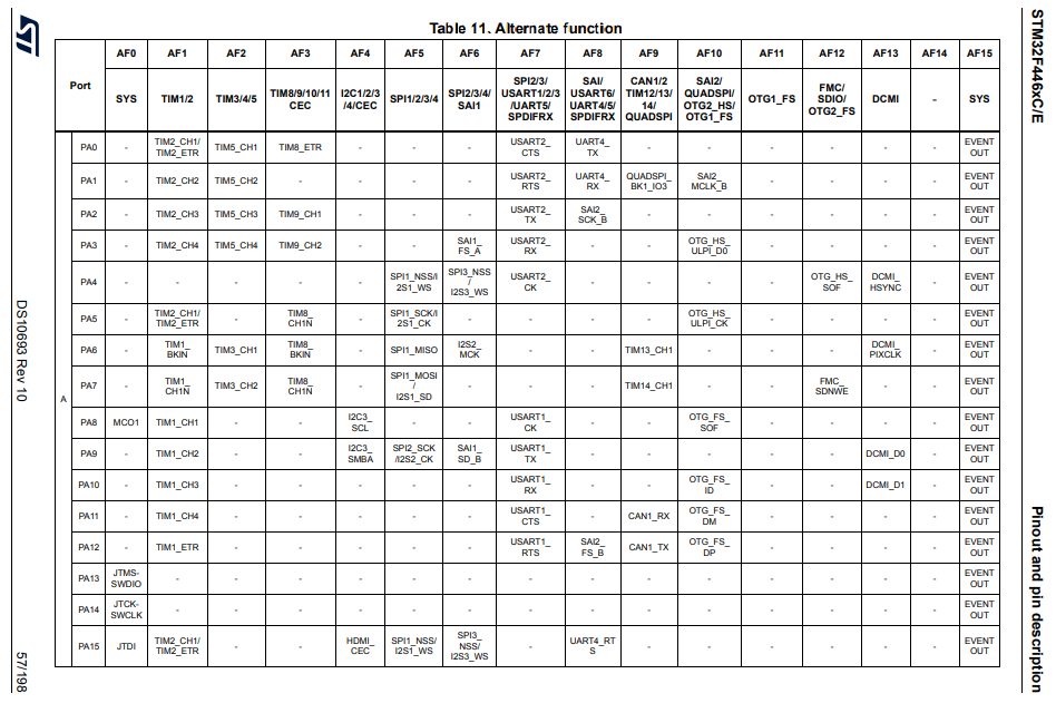
Looking at this table, you can see that PA0, PA5, and PA15 can all act as TIM2_CH1.
PA1 can function as TIM2_CH2
PA2 can function as TIM2_CH3
PA3 can function as TIM2_CH4
If there pins are configured for alternate function mode AF1, then we can project the timer's output onto these pins, so that these pins receive the waveform generated by the timer.
So being a channel of a timer is an alternate function of a GPIO pin.
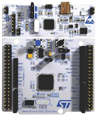
In this project, we will use pin PA5, because it has an onboard LED, which is what we will configure to toggle.
We need 2 major code files in order for this code to work.
We need our header file, which contains many macros and structures that describe the various registers and needed values.
We then need our main C file, which contains the code that puts timer 2 in output compare mode in a toggle state so that it can toggle an LED on and off every 1 second.
Below is the header file, which we name
stm32f407xx.h
The contents of the main.c file is shown below.
The first thing we must do is include the stdint.h header file and our stm32f446xx.h header file in our main.c file.
We create a function protoytpe for our tim2_pa5_output_compare() function, so that the compiler knows its return type, what arguments it accepts, along with its data type.
We then have our main() function, which simply consists of the timer function we have created.
So now we go to our timer function, which sets up the timer 2 in output capture mode.
In our timer function, the first thing we do is turn on the peripheral clock for the GPIO Port A, because pin PA5 is the pin we configure to be the timer channel we will use, which is TIM2_CH1
We then put pin PA5 in alternate function mode in the GPIO mode register.
We then use the AFRL register and set pin PA5 to function as TIM2_CH1, which is AF1.
Next, we enable the clock for the timer 2. The bus connected to the timer, TIM2, is the APB1 bus.
Next, we set the prescaler of the timer and the ARR, so that we get a signal of 1Hz, so that we have the LED turn off and on every 1 second.
Next, we go to the TIMx capture/compare mode register 1.
Within this register, we can specify that we want the compare mode to be Toggle.
The register is shown below.
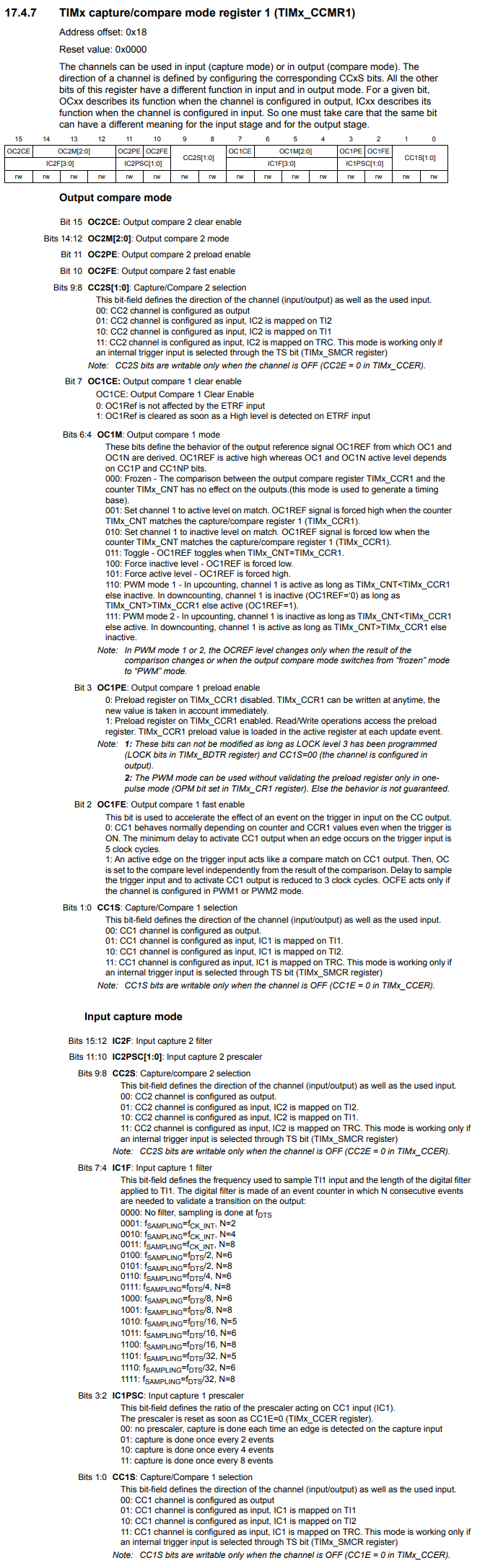
In the OC1M bits, bits 6:4, we set the mode to Toggle by setting these bits to 011.
We then now go to the TIMx capture/compare enable register, where we set channel 1 as the output channel that we want to use.
This register is shown below.
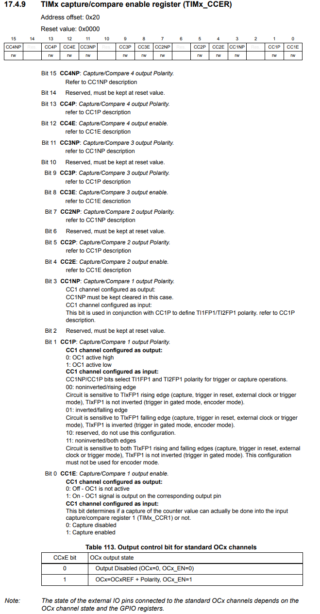
We write a 1 to bit 0, CC1E. Doing this makes channel 1 an output.
Remember that we are using TIM2_CH1.
In this register, you see 4 channels avaiable, because each timer has 4 channels. We have to select which channel we want to enable, which in this case is channel 1.
We then clear the timer counter register, so that is has no residual count.
We then enable the timer counter and start the process.
You should see that the onboard LED turns on and off each second.
This is the effect of the timer being in output compare mode, where it generates a toggling waveform, which feeds into pin PA5 to toggle the LED on and off.
This is one example of output compare mode.
So this is how we can toggle an LED on and off using the timer output compare mode in an STM32F446 microcontroller board in C.
Related Resources