
How to Transmit Data from Direct Memory Access (DMA) to a Peripheral Device with an STM32F446 Microcontroller Board in C
In this article, we show how to transmit data from Direct Memory Access (DMA) to a peripheral device with an STM32F446 microcontroller board in C.
Direct Memory Access (DMA) allows data transfers to take place in the background without the intervention of the Cortex-M processor. During this operation, the main processor can execute other tasks and it is only interrupted when a whole data block is available for processing. Therefore, large amounts of data can be transferred with no major impact on system performance.
So it is called direct memory access, because it can go directly to a peripheral device or memory as needed.
Whenever large amounts of data need to be transferred without desiring any drop in system performance, DMA can be a good solution.
According to the datasheet, Direct memory access (DMA) is used in order to provide high-speed data transfer between peripherals and memory and between memory and memory. Data can be quickly moved by DMA without any CPU action. This keeps CPU resources free for other operations. The DMA controller combines a powerful dual AHB master bus architecture with independent FIFO to optimize the bandwidth of the system, based on a complex bus matrix architecture.
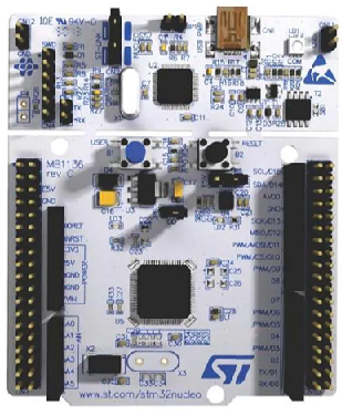
The STM32F446 microcontroller board has 2 DMA controllers (DMA1 and DMA2), which can be used for direct memory access.
Each DMA controller has 8 streams, and each of the streams has 8 channels. Therefore, each DMA controller has a possible 64 different configurations.
Whether you use DMA1 or DMA2 depends on which peripheral device you are working with.
For example, in our program, we stated that we want to use UART communication to send data from DMA to a peripheral device. Therefore, we need to configure a USART_TX pin. We do this for USART2_TX
There is something referred to as a DMA request mapping, which allows us to know which stream and which channel produces a certain configuration.
Look at the DMA requesting mapping below for DMA1 and DMA2.
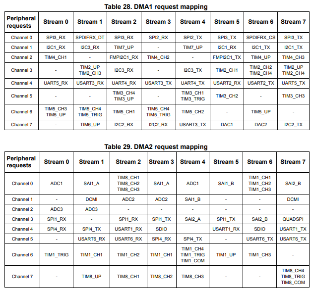
Looking at the DMA1 request mapping, you can see that if we select Stream 6 and Channel 4, we will have selected USART2_TX.
With this pin (with proper configuration), we can send data from DMA to a peripheral device via USART (or UART) communicadtion.
In this program, we will simply send data from direct memory access to RealTerm software using the UART communication protocol.
We transfer the data from the STM32 board to our computer via USB. With the particular pin of the STM32 board that we use as UART, the USB can carry the UART communication through its medium. There, for this program, we need very limited hardware, just the STM32 board, our computer, and the USB connection.
We need 2 major code files in order for this code to work.
We need our header file, which contains many macros and structures that describe the various registers and needed values.
We then need our main C file, which contains the code that allows us to transfer
Below is the header file that we will need for our code, which in this case is named,
stm32f446.h
So this header file contains all the definitions we need to create our main C file.
The contents of the main.c file is shown below.
The first thing we must do is include the stdint.h header file and our stm32f446xx.h header file in our main.c file.
Next we have a few function prototypes listed so that the compiler knows all of the functions in our program, the arguments they take in, the return value of the function, etc.
We then have our main() function.
Before we get to this function, let us first go into the others.
The usart2_tx_init() function sets pin PA2 to USART2_TX, turns on the USART2 clock, sets the baud rate for UART communication, enables the transmitter, and enables the USART.
The compute_usart_bd() function calculates the baud rate for UART communication.
Next, we have our dma1_stream6_init() function.
This function takes in 3 parameters: src, dst, and len.
The source is the origin of the data.
The dst is the destination of the data.
len is how many bits of data you are transmitting.
The first thing we do is enable clock access to DMA. This is done in the AHB1ENR register by setting bit 21 to HIGH.
The first thing we need to do is disable DMA1 Stream 6. According to the datasheet, before setting EN bit to 1 to start a new transfer, the event flags corresponding to the stream in DMA_LISR or DMA_HISR must be cleared.
We disable DMA1 Stream 6 by writing a 0 to bit 0 of the SxCR register, or the DMA stream x configuration register (DMA_SxCR).
This register is shown below.
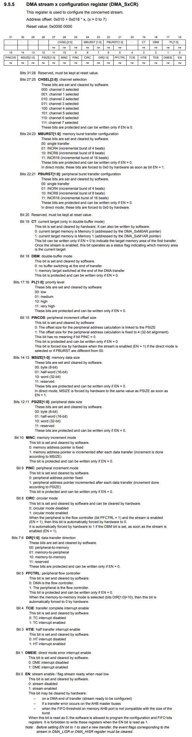
So this is a register we will be using frequently throughout the course of this program. It has many bits we need to configure in order to make this program work.
The first thing we need to do is clear bit 0, the EN bit (Stream enable). We do this through the following line, pDMA1->S6CR &= ~(1 << 0);
Just to make sure that the DMA1 Steam 6 has been disabled, we have the following while loop that waits until bit 0 is 0, while((pDMA1->S6CR) & (1 << 0));
As long as bit 0 is 1, the program will be stuck in that loop.
Next, we need to clear all interrupt flags for Stream 6.
We do this in the DMA high interrupt flag clear register (DMA_HIFCR) shown below.
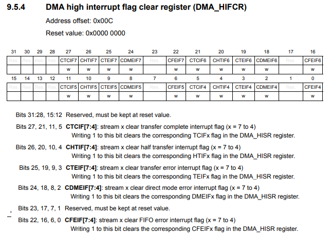
All of the bits that end in 6 belong to steam 6 and, thus, need to be cleared.
In this case, this would be bits 16, 18, 19, 20, and 21. So we do this in code. According to the datasheets, bits are cleared in this register by setting the bit HIGH.
Next, we need to set the destination buffer.
The destination buffer is the destination for where we want the data transferred from DMA to end up. In this case with this program, it is at the address of USART2.
We store this in the DMA stream x peripheral address register (DMA_SxPAR) shown below.
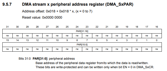
This register holds the address of the destination for where the data is going to.
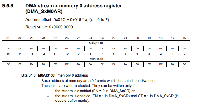
Next, we set the source buffer.
We store the source of the data in the DMA stream x memory 0 address register
(DMA_SxM0AR) shown below.
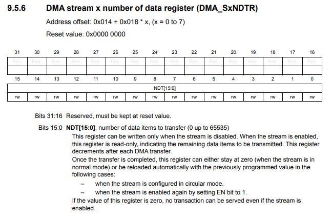
Next we set the length of the data being transferred in regard to the number of bits we are sending.
We set the length by writing this number to the
DMA stream x number of data register (DMA_SxNDTR) shown below.
Next we must select channel 4 as our desired configuration.
We do this in the configuration register, as we previously showed.
Bits 27:25 are the CHSEL, or channel selection bits. We want to select channel 4, so we write 100 to these bits.
Next, we must adjust the memory increment mode, bit 10, of the same configuration register. We want the memory address pointer to increment after each data transfer, so we set this bit HIGH. According to the datasheet, increment is done according to MSIZE. By default, MSIZE sends one byte (or 8 bits) at a time. You can adjust MSIZE as needed for your program to be a half-word (16 bits) or a word (32 bits). In this case, we are sending the default 8 bits.
Next we set the data transfer direction, bits 7:6 of the configuration register. Because we are sending data from DMA to a peripheral device, we set this bit to memory-to-peripheral. We write 01 to these 2 bits.
Next, we want an interrupt to be generated when the DMA transfer is complete. This means that we set bit 4, the TCIE (transfer complete interrupt enable) bit, to HIGH. This will trigger an interrupt once all of the data from DMA has been transferred to the peripheral device.
Next we want to disable FIFO mode and enable direct mode. We don't necessarily
want the data we entered first to be the last out. Instead we just want the data we
created to be transferred directly as is. So we are to able to do this by simply clearing
out the entire register.
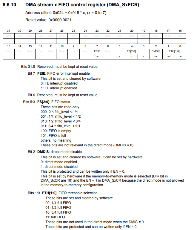
By clearing this register, we disable FIFO mode and enable direct mode.
Next, we enable DMA Stream 6 by setting bit 0, the EN (Stream Enable) bit, to HIGH in the configuration register.
Next, we need to enable USART2 transmitter for DMA.
This is done in the USART Control Register 3 shown below.
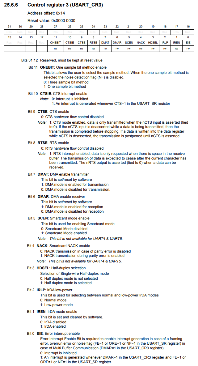
Looking at bit 7, the DMAT bit, this is how we can enable the DMA transmitter. By setting this bit to HIGH, DMA mode is enabled for transmission.
Lastly, we must enable the interrupt on the NVIC on the processor side.
Looking the value of the IRQ number up on the vector table, we see that the DMA has an IRQ number of 17.
This means that we must set the 17th bit to HIGH in the ISER0 register, which is what we do in the following line, *pNVIC_ISER0 |= (1 << 17);
Next, we go to our interrupt service routine for the DMA.
Remember that we trigger an interrupt after the complete DMA transfer is complete.
Once this transfer is completed, the interrupt service routine will be executed.
We need to check the DMA high interrupt status register (DMA_HISR) to check if the transfer is complete. This is done by checking if bit 21 is HIGH. Bit 21 is TCIF6, which the Transfer Complete Interrupt Flag for Stream 6.
If this bit is HIGH, we clear it in the DMA high interrupt flag clear register (DMA_HIFCR) by writing HIGH to bit 21.
We then turn on an LED just to show that this interrupt is executed in addition to transferring the data from DMA to the peripheral device.
Now we go back to our main() function.
Within this main() function, we create data that we are going to transfer.
This data is the variable, message, which is an array of type char, which has a length of 31.
Because we want to also turn on an LED in addition to sending the data when an interrupt occurs, we enable clock access to GPIOA and we set pin PA5 as an output pin.
We then initialize the UART communication through the line, usart2_tx_init();
We then use the dma1_stream6_int() function to send data from DMA to a peripheral device via UART communication.
We must specify 3 parameters with this function, including the data we are sending (in this case, message), the address of the destination (in this case, &pUSART2->DR), and the length of the data.
We then can execute our code and open the RealTerm software. Remember in the RealTerm software to specify a baud rate of 115200 and the correct USB port where your STM32 board is connected to.
Afterwards, you may have to open and close the port, and then you should see the message come through on the monitor.
And this is what is needed to transmit data from direct memory access to a peripheral device.
DMA comes especially in hand when you are transferring large amounts of data, so that
the CPU processing isn't tied down.
So this is how to transmit data from direct memory access to a peripheral
device with an STM32F446 microcontroller
board.
Related Resources