
How to Transmit Data with the UART Communication Protocol with an STM32F446 Microcontroller Board in C
In this article, we explain how to transmit data with the UART communication protocol with an STM32F446 microcontroller board in C.
UART stands for universal asynchronous receiver transmitter, and it is often used to transmit data between a microcontroller and various components.
UART, in its most basic form, only needs 2 pin connections: Tx (for transmission) and Rx (for receiving).
Some pins on the STM32 board are completely dedicated UART pins. Other pins are USART pins, which are UART pins but with the additional capability of being synchronous (in addition to asynchronous). So USART pins have dual capabilities in that they can be run synchronously (with a clock) or asynchronously ( without a clock).
If running asynchronously, the transmitting device (such as the STM32 microcontroller) and the receiving device must have the same baud rate (for uniform communication). If they don't have the same baud rate, the data will be corrupted
UART is best used for short distances.
In this example, we are going to use one of the USART pins in order to implement UART communication.
We will use the UART2_TX and UART2_RX pins, which are realized by pins PA2 and PA3 in alternate function modes.
Below is the alternate function mapping of the GPIO Port A of the STM32F446RE microcontroller.
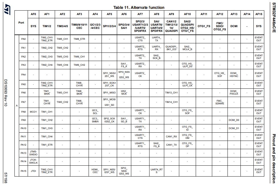
So you can see that if we put pins PA2 and PA3 in alternate function mode 7 (AF7), these pins will act as USART2_TX and USART2_RX.
If you look below these pins, you will see that pin PA4 can act as USART2_CK. However, in our circuit, we don't use this pin because we are using the USART2 pins in UART communication mode, which doesn't require a clock signal to communicate with the other device. If we were using the pin in USART mode, this CK pin would have to be configured and connected to the other device, so that communication could be established synchronously. However, in UART mode, a clock isn't needed. All that is needed is a baud rate that is the same for both the transmitting device and the receiving device.
There are also 2 more USART2 pins, UART2_CTS and UART2_RTS
These are pins that can stop the sending over of data in UART communication. They're for data flow control. The RTS pin of each device communicating via UART is cross coupled to the other's CTS pin. By placing the RTS pin to a HIGH logic state, the CTS pin of the device it is communicating with goes HIGH; this stops the module from sending the host data. Likewise, the module can stop the host sending data by taking its RTS HIGH, which takes the host's CTS HIGH.
The RTS and CTS require 2 extra wires when in configuration.
We will not be using them in our program.
Again, for this program, we will just be using the USART2_TX and USART2_RX pins, for use of the UART communication.
We don't actually have to do any connections at all.
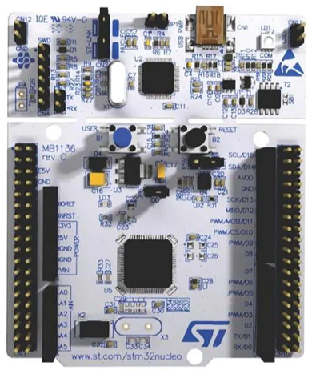
The great thing about using the USART2 pins is that we can transmit data using the UART protocol via USB.
So just connecting the STM32F446 board to your computer using a USB, you can intercept UART communication using a software. We will use the RealTerm software, which is a serial and TCP terminal for engineering and debugging.
We need 2 major code files in order for this code to work.
We need our header file, which contains many macros and structures that describe the various registers and needed values.
We then need our main C file, which contains the code that allows us to transmit data and receive data.
In this project, we will have a push button that is normally HIGH connected to GPIO pn PA6. When the push button is pressed, the logic state goes to a LOW state. During this LOW state, we will transmit data from our STM32 board to the RealTerm software. At the same time we are transmitting data, we can be receiving data, because UART has 2 separate lines for Tx and Rx.
Below is the header file that we will need for our code, which in this case is named,
stm32f407xx.h
So this header file contains all the definitions we need to create our main C file.
The contents of the main.c file is shown below.
The first thing we must do is include the stdint.h header file and our stm32f446xx.h header file in our main.c file.
Next we have a few function prototypes listed so that the compiler knows all of the functions in our program, the arguments they take in, the return value of the function, etc.
After this, we have our main() function.
Before we go to this main() function, let's look at the function definitions, starting with the usart2_tx_init() function.
This creates all the initializations needed in order to transmit data using the UART protocol.
The first thing we do in this function is turn on the peripheral clock for GPIO Port A. We need this on because we are using the USART2_TX and USART2_RX pins located on this port.
We then set pins PA2 to alternate function mode using the mode register.
We then set pin PA2 to alternate function mode 7 (AF7). This makes this pin acts as USART2_TX.
The next thing we do is we turn on the peripheral clock for USART2.
The next thing we do is we use a function, compute_uart_bd() to compute the baud rate for our device. Remember that we are using the USART pin for UART communication. UART communication depends on baud rate for proper communication between the host and the other device.
This function, which we will look at later, returns a 16-bit number that we place into the USART Baud Rate Register.
This register is shown below.
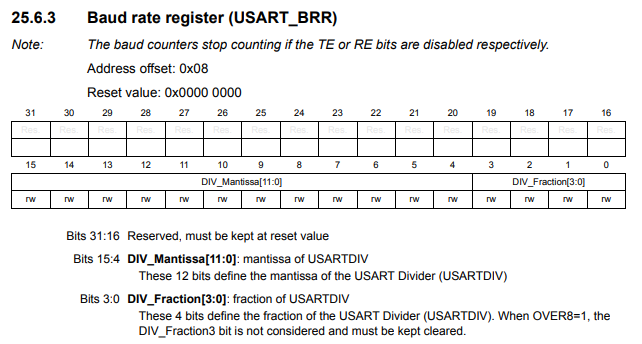
Now we have our baud rate fixed for our UART transmission.
Now for the device you are communicating with in the UART protocol needs to have the baud rate fixed to the same value, so that we can have faultless communication.
Next, we have to enable the transmitter for transmitting UART communication.
This is done with the TE bit, bit 3, of the USART control register 2.
The USART control register 1 is shown in the diagram below.
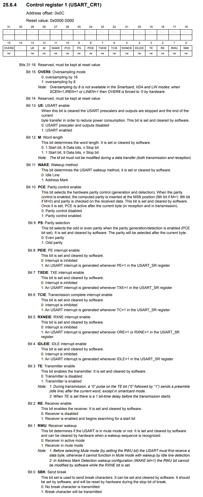
By setting the TE bit to HIGH, we enable the transmitter for transmission via UART (or USART).
The final thing we must do is enable the USART communication. This is done with the UE pin, pin 13, of the USART control register 1. By setting this bit to HIGH, we enable USART communication. Once this is done, UART communication commences. This is why this is the last step.
Next we have our code for the compute_uart_bd() function.
You can see that this is a simple function based on the baud rate (which is 115200) and the peripheral clock (which is 16000000). This function returns a 16-bit number, which we used to feed into the USART Baud Rate Register.
Next, we have our uart2_write() function.
Notice this function takes in a single parameter as input, an integer.
First, we must check that the transmit data register is empty. This is done by the line, while(!((pUSART2->SR) & (1 << 7)));
This is done by checking the TXE bit, bit 7, of the USART status register.
This register is shown in the diagram below.
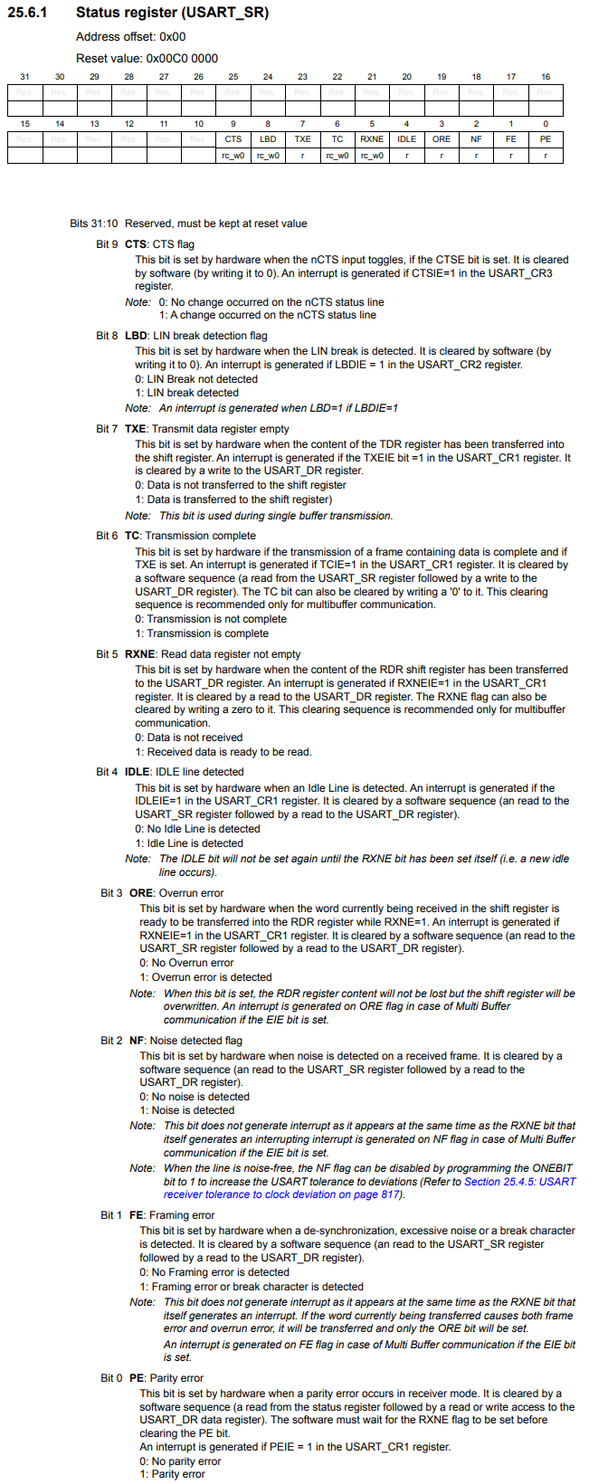
A 0 in the TXE bit means that data is not transferred to the shift register and, thus, the transmit data register is not empty.
A 1 in the TXE bit means that the data has been moved into the shift register and that the transmit data register is empty.
Once it is empty, we exit out of the while loop and go to the next section of code.
We write this value into the data register (DR).
This data register holds 8 bits.
You can see this in the diagram below.
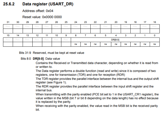
Because this register holds 8 bits, it can only hold a single character at once.
The int of a character converts the character into the ASCII equivalent of the character. By ANDing this number with all 1s (0xFF), we ensure that we have an 8-bit number that we can store within the data register.
We now go back to the main() function.
We first do all initializations with the statement, usart2_tx_init();
We then place within an infinite loop, usart2_write('Y');
This prints 'Y' in an infinite loop.
As stated before, we use the RealTerm software to detect the UART communication.
In this case, we are detecting the transmission of 'Y' in an infinite loop from our STM32 board to the RealTerm software.
Just remember to set the Baud Rate to 115200 on the RealTerm software and to select the appropriate USB port on your computer.
You may have to press the 'Open' button to close and reopen the port to reset the software. e c
You should then get a transmission of infinite 'Y'.
This is shown below.
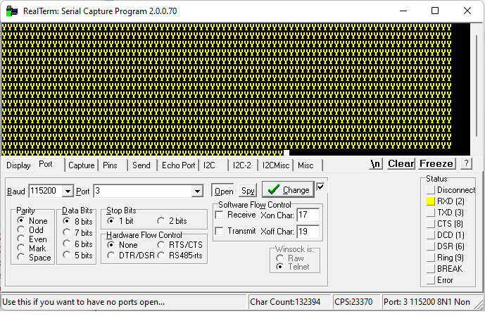
So you can see the character 'Y' printed out in an infinite loop.
Also note that we set the baud rate to 115200 to match the transmitting device, our STM32 board.
If not, the data would be corrupted and you would not see the 'Y' as output looped through infinitely.
So this is how to transmit data with the UART communication protocol with an STM32F446 microcontroller
board.
Related Resources