
How to Troubleshoot Common Problems with the I2C Communication Protocol
In this article, we explain how to troubleshoot common problems with the I2C communicaton protocol.
So when you are connecting a master device to a slave device to communicate via the I2C communication protocol, a number of issues can arise that can make the communication unsuccessful or simply not work.
Knowing how to troubleshoot issues with the I2C protocol, so that there can be successful communication between devices is crucial.
Below we have a number of things that should be done to ensure I2C communication is successful.
Ensure There is Power to the Master and Slave Devices
So the first thing that you must is ensure that the slave device is receiving sufficient power (as well as the master device).
Read the datasheet for the power requirements for the device in use and make sure that it is in the necessary range.
Some slave devices require 3.3V. Others may require 5V.
Make sure that the slave (and master) device receives the appropriate +V and GND connections to ensure power requirements.
Ensure There are Correct Value External Pull-up Resistors from the SCL and SDA Lines to +V
The SCL (clock) and SDA (data) lines need pull-up resistors connected to the +VDD.
Usually the resistors can be anywhere from 1K to 10K.
However, these resistor values may change depending on the frequency of the communication.
In certain cases, the datasheet may specify the value of the resistors needed, so checking the datasheet is advisable for resistors. If not, a rule of thumb is that a resistor between 1K and 10K should be sufficient for operation.
Generally, a safe resistor value to use is 4.7K for the pull-up resistors.
Do not go with a resistor value higher than 10K.
A common problem when using I2C communication is only using internal pull-up resistors with software. Always check the datasheet for the master device you are using to determine what pull-up resistor value is used for internal pull-up resistors. With STM32 boards, this is 40K. This would be too high of a resistor value for a pull-up resistor, thus it would not be sufficient to use this alone as pull-up resistors.
You can still use internal pull-up resistors. However, you must also use external resistors of the values specified above.
It is perfectly fine to use both internal and external resistors together, because in parallel, the total equivalent resistance is always lower than the smallest resistor in any of the branches.
The pull-up resistors are both for the SCL and SDA lines.
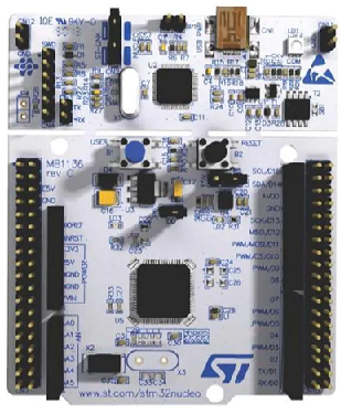
An example circuit is shown below depicting this.

Above is an example circuit of an STM32 board with an ADXL345 accelerometer.
Ensure That Correct Configuration of All Other Pins for I2C Communication on the Slave Device
One important factor that cannot be overlooked is all pins of the slave device must be configured correctly.
Slave devices require specific configuration for I2C (and SPI) configuration.
The setup for I2C configuration for a slave device should be specified in the datasheet for the slave device.
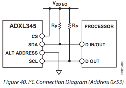
Below are the connections needed to establish I2C communication between the ADXL345 and a master device.
Without the other pins configured correctly, the circuit will not work.
According to the datasheet for the ADXL345 accelerometer, "I2C and SPI digital communications are available. In both cases, the ADXL345 operates as a slave. I2C mode is enabled if the CS pin is tied high to VDD I/O. The CS pin should always be tied high to VDD I/O or be driven by an external controller because there is no default mode if the CS pin is left unconnected. Therefore, not taking these precautions may result in an inability to communicate with the part. In SPI mode, the CS pin is controlled by the bus master. In both SPI and I2C modes of operation, data transmitted from the ADXL345 to the master device should be ignored during writes to the ADXL345. "
Also, on the datasheet, With CS tied high to VDD I/O, the ADXL345 is in I2C mode, requiring a simple 2-wire connection, as shown in Figure 40. The ADXL345 conforms to the UM10204 I 2C-Bus Specification and User Manual, Rev. 03—19 June 2007, available from NXP Semiconductors. It supports standard (100 kHz) and fast (400 kHz) data transfer modes if the bus parameters given in Table 11 and Table 12 are met. Single- or multiple-byte reads/writes are supported, as shown in Figure 41. With the ALT ADDRESS pin high, the 7-bit I2C address for the device is 0x1D, followed by the R/W bit. This translates to 0x3A for a write and 0x3B for a read. An alternate I2C address of 0x53 (followed by the R/W bit) can be chosen by grounding the ALT ADDRESS pin (Pin 12). This translates to 0xA6 for a write and 0xA7 for a read. There are no internal pull-up or pull-down resistors for any unused pins; therefore, there is no known state or default state for the CS or ALT ADDRESS pin if left floating or unconnected. It is required that the CS pin be connected to VDD I/O and that the ALT ADDRESS pin be connected to either VDD I/O or GND when using I2C."
So you can see that only when the
The other pin that is very important is the SDO/ALT ADDRESS pin. When the slave device is being addressed with the address 0x1D, then the SDO/ALT ADDRESS pin needs to be connected to VDD. If being addressed with the address 0x53, the SDO/ALT ADDRESS pin needs to be connected to GND.
So all other vital connections to establish I2C communication with the slave device must be done in order for successful communication.
Check with the datasheet for the diagram for proper I2C communication.
Software checks
So now that we have gone through the hardware requirements, we will now go over the software requirements for I2C communication.
The SCL and SDA Pins Must Be In Open Drain Configuration
The SCL and SDA pins must be configured in open drain mode.
I2C communication always operates in open drain configuration and not in push-pull configuration.
Clock Access Must Be Established to I2C
Make sure that clock access is enabled for I2C.
Without clock access to I2C, it will generate no clock signal on the SCL line.
Once clock access has been established to I2C, we then set the clock frequency, its data transfer mode, and its
rise time.
So these are the most common and most important tips for troubleshooting problems with the I2C communication protocol between a master and slave device.
Hardware connections must be all set up precisely, and software must have all necessary set up as well.
Related Resources