
How the I2C Communication Protocol Works
In this article, we explain how the I2C communication protocol works.
The I2C communication protocol allows 2 devices to communicate, a master and slave, to communicate.
The I2C, which stands for Inter-Integrated Circuit, communication protocol is a two-wire interface protocol that has 2 lines of transmission, SCL and SDA.
SCL is the serial clock line, which is used for synchronizing data transfer between the master and slave.
SDA is the serial data line, which is used to transfer the data.
The operation modes of the I2C protocol is either Master Transmitter, Master Receiver, Slave Transmitter, or Slave Receiver.
With the I2C protocol, transactions are initiated and completed by the master device.
All messages have an address frame and a data frame.
Data is placed on the SDA line after SCL goes LOW, and it is sampled after the SCL line goes HIGH.
Below is a diagram showing I2C communication protocol.
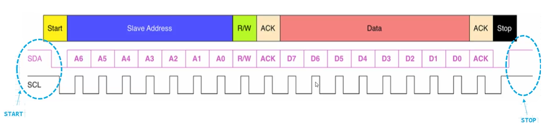
As shown in the diagram above, all transactions begin with START and are terminated by STOP.
A HIGH to LOW transition on the SDA line while SCL is HIGH defines a START condition.
A LOW to HIGH transition on the SDA line while SCL is HIGH defines a STOP condition.
START and STOP conditions are always generated by the master.
The bus is considered to be free again a certain time after the STOP condition.
The bus stays busy if a repeated START is generated instead of a STOP condition.
Any information transmitted on the SDA line must be 8 bits long (1 byte).
The number of bytes that can be transmitted per transfer is unrestricted.
Each byte must be followed by an Acknowledge (ACK) bit.
Data is transferred with the Most Significant Bit (MSB) first.
The address frame is first in any new communication sequence.
For a 7-bit address, the address is sent out most significant bit (MSB) first, followed by a R/W bit indicating whether this is a read (1) or a write (0) operation.
Remember that multiple slave devices can be connected to a master. This is the reason why addressing is needed to begin with.
The address specifies which slave the master is communicating with. The address is how the master selects a particular slave on its bus.
The data frame begins transmission after the address frame is sent.
The master will simply continue generating clock pulses on SCL at a regular interval, and the data will be placed on SDA by either the master or the slave, depending on whether the R/W bit indicated a read or write operation.
If the R/W bit is set to 1 (read operation), then the slave adds the data to the SDA line for the master to read.
If the R/W bit is set to 0 (write operation), then the master adds the data to the SDA line for the slave to read.
One more thing that is worth nothing is that we can define the clock speed of the I2C communication protocol.
The I2C clock speed is the speed of the I2C interface and should correspond with the bus speeds defined in the I2C specification.
Standard mode is a speed of 100KHz max.
Fast-mode is a speed of 400KHz max.
Fast-mode plus is a speed of 1MHz.
High-speed mode is a speed of 3.4MHz.
Depending on the needs of the specific devices communicating determines
the needed speed requirements.
And this is how the I2C communication protocol works.
The I2C communication protocol is used frequently with microcontrollers such as STM32 boards communicating with sensors that use the I2C protocol.
Related Resources