How to Connect an I2C Device to an Arduino Microcontroller
In this project, we will show how to connect an I2C device to an arduino microcontroller.
The I2C bus is a bus which enables high-speed two-way communication between devices while using a minimal number of I/O pins to facilitate communication.
An I2C bus is controlled by a master device (usually a microcontroller) and contains one ore more slave devices that receive information from the master device.
The I2C protocol was created by Phillips in the early 1980s and was standardized and adopted widespread in the 1990s. The protocol is known as the "two-wire" protocol because 2 lines are used for communication. These 2 lines are the clock line and data line.
I2C protocol can incorporate multiple devices that all share the same communication lines: a clock signal (SCL) and a bidirectional data line used for sending information back and forth between the master and slave (SDA).
In order to work, the 2 lines of the I2C, the clock and data lines, need pull-up resistors to the positive voltage source.
The diagram below shows the connection of an I2C master device to its slave device.
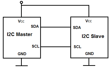
All that is necessary is for the master and slave each to get the power that it needs (VCC and GND) and for the clock and data lines to be tied together. So the SCLK line from the master device connects to the SCLK on the slave device. And the SDA line from the master device connects to the SDA line on the slave device.
The Arduino acts as the master device. The bus master is responsible for initiating all communications. Slave devices cannot initiate communications; they only respond to requests that are sent by the master device. This prevents multiple slave devices from all trying to communicate at the same thing, causing garbled messages.
When a command or request is sent out by the master device, it is received by all slave devices on the bus. Each I2C device has a unique 7-bit address, or ID number. When communication is initiated by the master device, a device ID is transmitted. I2C slave devices react to data on the bus only when it is drected at their ID number. Since all the devices are receiving all the data transmitted by the master device, each device has to have a unique ID number so that the master can speak to a particular slave device.
Some I2C devices have selectable addresses whereas others come form the manufacturer with a fixed address.
An example of an I2C device that has fixed addresses is the TC74 temperature sensor. This means that the addresses are fixed by the manufacturer. However, just because it is fixed doesn't mean you can't have multiple TC74 sensors connected together. It's possible to connect possible sensors to an I2C bus by purchasing this IC with eight different ID numbers. So you could connect up to eight of them on a single bus. Each of the 8 lines having different addresses.
Other I2C, such as the AD7414 and AD7415, have address select (AS) pins that allow you to configure the I2C address of the device.
the basic steps for controlling any I2C device are as follows.
- The Master device sends a start bit
- The Master sends 7-bit slave address of the slave device it wants to talk to
- The Master sends a read (1) or write (0) bit depending on whether it wants to write data into an I2C device's register or if it wants to read from one of the I2C device's registers.
- The Slave device then responds with an "acknowledge" or ACK bit (a logic low)
- In write mode, the master sends 1 byte of information at a time, and slave responds with ACKs. In read mode, the master receives 1 byte of information at a time and sends an ACK to the slave after each byte
- When communication has been completed, the master sends a stop bit
Components
- TC74 Temperature Sensor
- 2 4.7KΩ resistors
- Arduino microcontroller
The TC74 temperature we use specifically is the TC74A0-5.0VAT sensor.
This sensor runs on 5V on power.
The TC74 sensor has 5 pins.
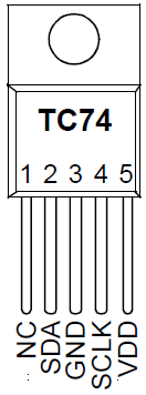
The NC pin is just a Not Connected pin. It doesn't connect to our circuit.
The SDA is the serial data pin. This is how the arduino microcontroller and the temperature sensor share data with each other. Data is shared bidirectionally.
The third pin is the power ground pin.
The fourth pin is the SCLK pin. This allows for communication on a clock signal.
And the fifth pin is VDD, which gets connected +5V.
Circuit Connecting an I2C TC74 Temperature Sensor to an Arduino Microcontroller
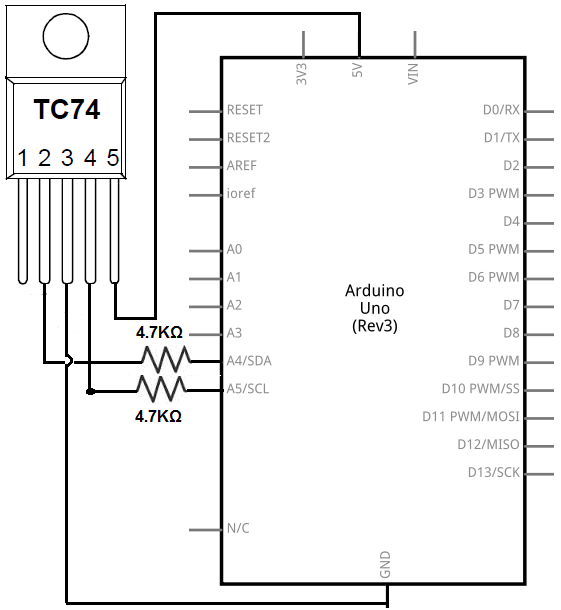
The I2C temperature sensor circuit we will build with an Arduino is shown below.
This above circuit built on a breadboard is shown below.
In this circuit, the hardware connections are very simple.
Pin 1 is NC, which means Not Connected. So we leave that pin unconnected.
Pin 2 is the SDA pin, which is the Serial Data pin. This transmits data bidirectionally between the master device and the slave device. The SDA pin connects to analog pin 4 on the arduino.
Pin 3 is the power ground, so it connects to the ground terminal of the arduino.
Pin 4 is the SCLK pin, which is the Serial Clock pin. This pin clocks data into and out of the TC74 sensor.
Pin 5 is the VDD pin, which is the positive voltage power source for the sensor. It connects to the +5V pin of the arduino.
And these complete the hardware connections from the arduino microcontroller to the I2C sensor.
Code
The code so that we can connect the I2C TC74 sensor to an arduino microcontroller is shown below.
Arduino's I2C communication library is called the Wire library. With this library, you can easily write to and read from I2C devices.
#include <Wire.h>
int address= 72;
void setup(){
Serial.begin(9600);
Wire.begin();
}
void loop(){
Wire.beginTransmission(address);
Wire.write(0);
Wire.endTransmission();
Wire.requestFrom(address, 1);
while(Wire.available() == 0);
int celsius= Wire.read();
int fahrenheit= round(celsius * 9.0/5.0 + 32.0);
Serial.print(celsius);
Serial.print("degrees celsius ");
Serial.print(fahrenheit);
Serial.print(" degrees Fahrenheit");
delay(1000);
}
First, we import the Wire library, which is the library for communicating with I2C devices.
Next, we initialize the value of the address which we want to communicate. The TC74 sensors that run on 5V comes in 8 different IC packages. These are TC74A0 to TC74A7. Depending on which TC74 sensor you use determines the address that we will initialize to. The TC74 datasheet has all the addresses listed for all the various TC74s. Therefore, you just need to look up the address on the datasheet. Being that we are using a TC74A0, the address is 1001000; the decimal equivalent of this is 72. Therefore, we initialize the address to 72.
Next, we have the setup() function. This creates the Serial monitor where we can see the reading of our temperature. And we create a Wire object, which allows for communication between the master and slave device.
Next, we have our loop() function. We begin a transmission in which we communicate with the device at the address we initially specified. This allows the master device to communicate with the slave device (at that address). This is how we distinguish communication if we have multiple slave devices, by the address.
Next, we send a bit asking for register 0 of the TC74, which is the data register of the sensor. We will then read from this data register to find out the temperature. We then end the transmission of data from the master to the slave device.
We then request 1 byte from the TC74 sensor. This value will come in the value celsius. We then calculate the fahrenheit based on this celsius value. And then print out the values in both celsius and fahrenehit.
We give 1-second delay between readings.
This circuit demonstrates how an I2C device connects to an arduino microcontroller and how we can easily write and read to the device in code.
Related Resources
How to Connect Multiple I2C Devices to an Arduino Microcontroller