I/O Registers of an Embedded Microcontroller- Explained
In this article, we go over what I/O registers are and what they are used for in embedded microcontroller applications.
All microcontrollers have data memory. This is the memory that a microcontroller uses when it is executing a program that has been uploaded to it. The data memory is really the working memory during program (code) execution.
Data memory is read/write memory, so they can be written to and read from.
The data memory of an Atmel AVR processor typically contains 3 areas of memory. The lowest section contains the 32 general-purpose working registers, followed by 64 I/O registers, then followed by the internal SRAM memory.
The working registers are used as a local storage area while the program is executing. The 64 I/O registers are used as an interface
to the I/O devices and peripherals on board the microcontroller. And the internal SRAM is used as a general variables storage area and also
for the processor stack.
I/O Registers of Data Memory
As stated, in the ATMega16, the 64 registers after the 32 general-purpose working registers are the I/O registers.
Below is a diagram of the data memory of an AtMega16 processor.
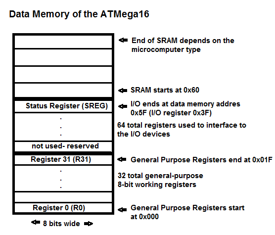
The I/O registers each provide access to the control registers or the data registers of the I/O peripherals contained within the micrcontroller.
The porgrammer uses the I/O registers extensively to provide interface to the I/O peripherals of the microcontroller. Other Ateml devices such as the ATMega128 have more memory reserved for I/O registers. So they will not fit into the 64-byte space. These devices occupy space up to 0x100 to accomodate the larger number of I/O registers.
The table below shows a selection of I/O registers, emphasizing those associated with parallel ports.
| I/O Register Name |
I/O
Register Address |
SRAM
Address |
Description |
| DDRA | 0x1A | 0x3A | Data Direction Register for Port A |
| DDRB | 0x17 | 0x37 | Data Direction Register for Port B |
| PORTA | 0x1B | 0x3B | Output Latches for Port A |
| PINB | 0x16 | 0x36 | Input Pins for Port B |
| SREG | 0x3F | 0x5F | Processor Status Register |
Each I/O register has a name, I/O address, and an SRAM address.
A C language programmer will most commonly use the I/O register name. The two different numeric addresses are important when writing in assembly language because some of the instructions relate to the SRAM address and some relate to the I/O address.
The I/O register names are much more conveninet for the C language programmer to use than the addresses. However, the C language compiler does not inherently know what these names are or know what addresses to associate with the names. Each program should contain an #include header file that defines the names and the associated addresses for the C language compiler.
The C program below demonstrates this: The program reads the pins of Port B using the PINB I/O register and writes the results to
the output latches of Port A using the PORTA register. The C compiler gets the addresses
to use with these registers from the #include header file
in the first line of the program, which in this case is, mega16.h.
In summary, the C language programmer uses the I/O registers as the interface
to the I/O hardware devices within the microcontroller. Later we will discuss the use and function
of each of the I/O peripherals in the microcontroller and their associated I/O registers.
#include
main()
{
DDRA= 0xFF;
//all bits are input
while(1)
{
PORTA= PINB;
}
}